
- Short to ground
- +B short
| Last Modified: 02-14-2025 | 6.11:8.1.0 | Doc ID: RM1000000015GUI |
| Model Year Start: 2018 | Model: Camry HV | Prod Date Range: [07/2017 - 10/2020] |
| Title: PARK ASSIST / MONITORING: BLIND SPOT MONITOR SYSTEM: U0232; Lost Communication with Blind Spot Monitor Slave Module; 2018 - 2020 MY Camry HV [07/2017 - 10/2020] | ||
|
DTC |
U0232 |
Lost Communication with Blind Spot Monitor Slave Module |
DESCRIPTION
This DTC is stored when the blind spot monitor sensor RH judges that there is a communication problem with the blind spot monitor sensor LH.
|
DTC No. |
Detection Item |
DTC Detection Condition |
Trouble Area |
|---|---|---|---|
|
U0232 |
Lost Communication with Blind Spot Monitor Slave Module |
The blind spot monitor sensor (master) cannot receive signals from the blind spot monitor sensor (slave) |
|
- *: w/ Intelligent Clearance Sonar System
WIRING DIAGRAM
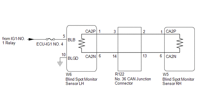
w/ Intelligent Clearance Sonar System
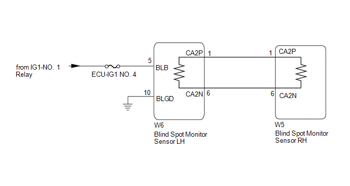
w/o Intelligent Clearance Sonar System
CAUTION / NOTICE / HINT
NOTICE:
- When checking for DTCs, make sure that the blind spot monitor system is turned on.
- Inspect the fuses for circuits related to this system before performing the following procedure.
- Before measuring the resistance of the CAN bus, turn the power switch off and leave the vehicle for 1 minute or more without operating the key or any switches, or opening or closing the doors. After that, disconnect the cable from the negative (-) auxiliary battery terminal and leave the vehicle for 1 minute or more before measuring the resistance.
-
After turning the power switch off, waiting time may be required before disconnecting the cable from the negative (-) auxiliary battery terminal. Therefore, make sure to read the disconnecting the cable from the negative (-) auxiliary battery terminal notices before proceeding with work.
Click here
![2018 - 2019 MY Camry HV [07/2017 - 09/2019]; INTRODUCTION: REPAIR INSTRUCTION: PRECAUTION](/t3Portal/stylegraphics/info.gif)
HINT:
- Operating the power switch, any other switches or a door triggers related ECU and sensor communication on the CAN. This communication will cause the resistance value to change.
- Even after DTCs are cleared, if a DTC is stored again after driving the vehicle for a while, the malfunction may be occurring due to vibration of the vehicle. In such a case, wiggling the ECUs or wire harness while performing the inspection below may help determine the cause of the malfunction.
PROCEDURE
|
1. |
CONFIRM MODEL |
(a) Choose the model to be inspected.
|
Result |
Proceed to |
|---|---|
|
w/ Intelligent Clearance Sonar System |
A |
|
w/o Intelligent Clearance Sonar System |
B |
| B |

|
|
|
2. |
CHECK DTC OUTPUT (INTELLIGENT CLEARANCE SONAR SYSTEM) |
(a) Using the Techstream, check for DTCs according to the prompts on the screen.
Body Electrical > Advanced Parking Guidance/ICS/Intuitive P/A > Trouble Codes
Standard:
The clearance warning ECU assembly does not output DTCs U0232 and U0233 simultaneously.
| NG |
|
|
|
3. |
CHECK CAN BUS MAIN WIRE |
(a) Turn the power switch off.
(b) Disconnect the cable from the negative (-) auxiliary battery terminal.
|
(c) Measure the resistance according to the value(s) in the table below. Standard Resistance:
|
|
(d) Reconnect the cable to the negative (-) auxiliary battery terminal.
|
Result |
Proceed to |
|---|---|
|
OK |
A |
|
Open circuit in CAN main bus lines |
B |
|
Short circuit between bus lines |
C |
|
|
D |
| B |
|
| C |
|
| D |
|
|
|
4. |
CHECK HARNESS AND CONNECTOR (BLIND SPOT MONITOR SENSOR LH - BODY GROUND) |
Click here
| NG |
|
REPAIR OR REPLACE HARNESS OR CONNECTOR |
|
|
5. |
CHECK HARNESS AND CONNECTOR (BLIND SPOT MONITOR SENSOR LH - POWER SOURCE) |
Click here
| NG |
|
REPAIR OR REPLACE HARNESS OR CONNECTOR |
|
|
6. |
CHECK DTC |
(a) Turn the power switch off.
(b) Turn the power switch on (IG).
(c) Check for DTCs.
Body Electrical > Blind Spot Monitor Master > Trouble Codes
OK:
No DTCs are output.
| OK |
|
SYMPTOM SIMULATION
|
| NG |
|
|
7. |
CHECK FOR OPEN IN CAN BUS MAIN WIRE (No. 36 CAN JUNCTION CONNECTOR) |
|
(a) Disconnect the R122 No. 36 CAN junction connector. |
|
(b) Measure the resistance according to the value(s) in the table below.
Standard Resistance:
|
Tester Connection |
Condition |
Specified Condition |
|---|---|---|
|
R122-3 (CANH) - R122-14(CANL) |
Cable disconnected from negative (-) auxiliary battery terminal |
108 to 132 Ω |
|
R122-2 (CANH) - R122-13(CANL) |
Cable disconnected from negative (-) auxiliary battery terminal |
108 to 132 Ω |
|
Result |
Proceed to |
|---|---|
|
OK |
A |
|
NG (to blind spot monitor sensor RH CAN main wire) |
B |
|
NG (to blind spot monitor sensor LH CAN main wire) |
C |
| A |
|
REPLACE No. 6 CAN JUNCTION CONNECTOR |
| C |
|
|
|
8. |
CHECK FOR OPEN IN CAN BUS MAIN WIRE (BLIND SPOT MONITOR SENSOR RH) |
(a) Reconnect the R122 No. 36 CAN junction connector.
|
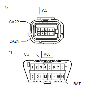
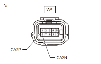
(b) Disconnect the W5 blind spot monitor sensor RH connector. |
|

(c) Measure the resistance according to the value(s) in the table below.
Standard Resistance:
|
Tester Connection |
Condition |
Specified Condition |
|---|---|---|
|
W5-1 (CA2P) - W5-6 (CA2N) |
Cable disconnected from negative (-) auxiliary battery terminal |
108 to 132 Ω |
| OK |
|
| NG |
|
REPAIR OR REPLACE CAN MAIN WIRE OR CONNECTOR (BLIND SPOT MONITOR SENSOR RH - No. 6 CAN JUNCTION CONNECTOR) |
|
9. |
CHECK FOR OPEN IN CAN BUS MAIN WIRE (BLIND SPOT MONITOR SENSOR LH) |
(a) Reconnect the R122 No. 36 CAN junction connector.
|
(b) Disconnect the W6 blind spot monitor sensor LH connector. |
|
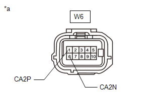
(c) Measure the resistance according to the value(s) in the table below.
Standard Resistance:
|
Tester Connection |
Condition |
Specified Condition |
|---|---|---|
|
W6-1 (CA2P) - W6-6 (CA2N) |
Cable disconnected from negative (-) auxiliary battery terminal |
108 to 132 Ω |
| OK |
|
| NG |
|
REPAIR OR REPLACE CAN MAIN WIRE OR CONNECTOR (BLIND SPOT MONITOR SENSOR LH - No. 6 CAN JUNCTION CONNECTOR) |
|
10. |
CHECK FOR SHORT IN CAN BUS WIRES (No. 36 CAN JUNCTION CONNECTOR) |
|
(a) Disconnect the R122 No. 36 CAN junction connector. |
|
(b) Measure the resistance according to the value(s) in the table below.
Standard Resistance:
|
Tester Connection |
Condition |
Specified Condition |
|---|---|---|
|
R122-3 (CANH) - R122-14 (CANL) |
Cable disconnected from negative (-) auxiliary battery terminal |
108 to 132 Ω |
|
R122-2 (CANH) - R122-13 (CANL) |
Cable disconnected from negative (-) auxiliary battery terminal |
108 to 132 Ω |
|
Result |
Proceed to |
|---|---|
|
OK |
A |
|
NG (to blind spot monitor sensor RH CAN main wire) |
B |
|
NG (to blind spot monitor sensor LH CAN main wire) |
C |
| A |
|
REPLACE No. 6 CAN JUNCTION CONNECTOR |
| C |
|
|
|
11. |
CHECK FOR SHORT IN CAN BUS WIRES (BLIND SPOT MONITOR SENSOR RH) |
(a) Reconnect the R122 No. 36 CAN junction connector.
|
(b) Disconnect the W5 blind spot monitor sensor RH connector. |
|
(c) Measure the resistance according to the value(s) in the table below.
Standard Resistance:
|
Tester Connection |
Condition |
Specified Condition |
|---|---|---|
|
W5-1 (CA2P) - W5-6 (CA2N) |
Cable disconnected from negative (-) auxiliary battery terminal |
108 to 132 Ω |
| OK |
|
| NG |
|
REPAIR OR REPLACE CAN MAIN WIRE OR CONNECTOR (BLIND SPOT MONITOR SENSOR RH - No. 6 CAN JUNCTION CONNECTOR) |
|
12. |
CHECK FOR SHORT IN CAN BUS WIRES (BLIND SPOT MONITOR SENSOR LH) |
(a) Reconnect the R122 No. 36 CAN junction connector.
|
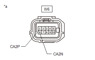
(b) Disconnect the W6 blind spot monitor sensor LH connector. |
|
(c) Measure the resistance according to the value(s) in the table below.
Standard Resistance:
|
Tester Connection |
Condition |
Specified Condition |
|---|---|---|
|
W6-1 (CA2P) - W6-6 (CA2N) |
Cable disconnected from negative (-) auxiliary battery terminal |
108 to 132 Ω |
| OK |
|
| NG |
|
REPAIR OR REPLACE CAN MAIN WIRE OR CONNECTOR (BLIND SPOT MONITOR SENSOR LH - No. 6 CAN JUNCTION CONNECTOR) |
|
13. |
CHECK FOR SHORT IN CAN BUS WIRES (No. 36 CAN JUNCTION CONNECTOR) |
(a) Disconnect the R122 No. 36 CAN junction connector.
(b) Measure the resistance according to the value(s) in the table below.
|
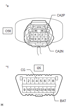
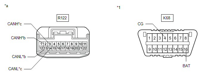
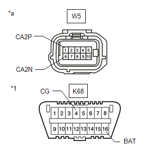
*1 |
DLC3 |
- |
- |
|
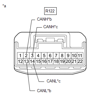
*a |
Front view of wire harness connector (to No. 36 CAN Junction Connector) |
*b |
to blind spot monitor sensor RH CAN main wire |
|
*c |
to blind spot monitor sensor LH CAN main wire |
- |
- |
Standard Resistance:
|
Tester Connection |
Condition |
Specified Condition |
|---|---|---|
|
R122-3 (CANH) - K68-4 (CG) |
Cable disconnected from negative (-) auxiliary battery terminal |
200 Ω or higher |
|
R122-14 (CANL) - K68-4 (CG) |
Cable disconnected from negative (-) auxiliary battery terminal |
200 Ω or higher |
|
R122-3 (CANH) - K68-16 (BAT) |
Cable disconnected from negative (-) auxiliary battery terminal |
6 kΩ or higher |
|
R122-14 (CANL) - K68-16 (BAT) |
Cable disconnected from negative (-) auxiliary battery terminal |
6 kΩ or higher |
|
R122-2 (CANH) - K68-4 (CG) |
Cable disconnected from negative (-) auxiliary battery terminal |
200 Ω or higher |
|
R122-13 (CANL) - K68-4 (CG) |
Cable disconnected from negative (-) auxiliary battery terminal |
200 Ω or higher |
|
R122-2 (CANH) - K68-16 (BAT) |
Cable disconnected from negative (-) auxiliary battery terminal |
6 kΩ or higher |
|
R122-13 (CANL) - K68-16 (BAT) |
Cable disconnected from negative (-) auxiliary battery terminal |
6 kΩ or higher |
|
Result |
Proceed to |
|---|---|
|
OK |
A |
|
NG (to blind spot monitor sensor RH CAN main wire) |
B |
|
NG (to blind spot monitor sensor LH CAN main wire) |
C |
| A |
|
REPLACE No. 6 CAN JUNCTION CONNECTOR |
| C |
|
|
|
14. |
CHECK FOR SHORT IN CAN BUS WIRES (BLIND SPOT MONITOR SENSOR RH) |
(a) Reconnect the R122 No. 36 CAN junction connector.
(b) Disconnect the W5 blind spot monitor sensor RH connector.
|
(c) Measure the resistance according to the value(s) in the table below. Standard Resistance:
|
|
| OK |
|
| NG |
|
REPAIR OR REPLACE CAN MAIN WIRE OR CONNECTOR (BLIND SPOT MONITOR SENSOR RH - No. 6 CAN JUNCTION CONNECTOR) |
|
15. |
CHECK FOR SHORT IN CAN BUS WIRES (BLIND SPOT MONITOR SENSOR LH) |
(a) Reconnect the R122 No. 36 CAN junction connector.
(b) Disconnect the W6 blind spot monitor sensor LH connector.
|
(c) Measure the resistance according to the value(s) in the table below. Standard Resistance:
|
|

| OK |
|
| NG |
|
REPAIR OR REPLACE CAN MAIN WIRE OR CONNECTOR (BLIND SPOT MONITOR SENSOR LH - No. 6 CAN JUNCTION CONNECTOR) |
|
16. |
CHECK CAN BUS MAIN WIRE |
(a) Turn the power switch off.
(b) Disconnect the cable from the negative (-) auxiliary battery terminal.
|
(c) Measure the resistance according to the value(s) in the table below. Standard Resistance:
|
|
(d) Reconnect the cable to the negative (-) auxiliary battery terminal.
|
Result |
Proceed to |
|---|---|
|
OK |
A |
|
Open circuit in CAN main bus lines |
B |
|
Short circuit between bus lines |
C |
|
D |
| B |
|
| C |
|
| D |
|
|
|
17. |
CHECK HARNESS AND CONNECTOR (BLIND SPOT MONITOR SENSOR LH - BODY GROUND) |
Click here
| NG |
|
REPAIR OR REPLACE HARNESS OR CONNECTOR |
|
|
18. |
CHECK HARNESS AND CONNECTOR (BLIND SPOT MONITOR SENSOR LH - POWER SOURCE) |
Click here
| NG |
|
REPAIR OR REPLACE HARNESS OR CONNECTOR |
|
|
19. |
CHECK DTC |
(a) Turn the power switch off.
(b) Turn the power switch on (IG).
(c) Check for DTCs.
Body Electrical > Blind Spot Monitor Master > Trouble Codes
OK:
No DTCs are output.
| OK |
|
SYMPTOM SIMULATION
|
| NG |
|
|
20. |
CHECK FOR OPEN IN CAN BUS MAIN WIRE (BLIND SPOT MONITOR SENSOR LH) |
(a) Disconnect the cable from the negative (-) auxiliary battery terminal.
|
(b) Disconnect the W6 blind spot monitor sensor LH connector. |
|
(c) Measure the resistance according to the value(s) in the table below.
Standard Resistance:
|
Tester Connection |
Condition |
Specified Condition |
|---|---|---|
|
W6-1 (CA2P) -W6-6 (CA2N) |
Cable disconnected from negative (-) auxiliary battery terminal |
108 to 132 Ω |
| OK |
|
|
|
21. |
CHECK FOR OPEN IN CAN BUS MAIN WIRE (BLIND SPOT MONITOR SENSOR RH) |
(a) Reconnect the W6 blind spot monitor sensor LH connector.
|
(b) Disconnect the W5 blind spot monitor sensor RH connector. |
|
(c) Measure the resistance according to the value(s) in the table below.
Standard Resistance:
|
Tester Connection |
Condition |
Specified Condition |
|---|---|---|
|
W5-1 (CA2P) - W5-6 (CA2N) |
Cable disconnected from negative (-) auxiliary battery terminal |
108 to 132 Ω |
| OK |
|
| NG |
|
REPAIR OR REPLACE CAN MAIN WIRE OR CONNECTOR (BLIND SPOT MONITOR SENSOR RH - BLIND SPOT MONITOR SENSOR LH) |
|
22. |
CHECK FOR SHORT IN CAN BUS WIRES (BLIND SPOT MONITOR SENSOR LH) |
(a) Disconnect the cable from the negative (-) auxiliary battery terminal.
|
(b) Disconnect the W6 blind spot monitor sensor LH connector. |
|
(c) Measure the resistance according to the value(s) in the table below.
Standard Resistance:
|
Tester Connection |
Condition |
Specified Condition |
|---|---|---|
|
W6-1 (CA2P) -W6-6 (CA2N) |
Cable disconnected from negative (-) auxiliary battery terminal |
108 to 132 Ω |
| OK |
|
|
|
23. |
CHECK FOR SHORT IN CAN BUS WIRES (BLIND SPOT MONITOR SENSOR RH) |
(a) Reconnect the W6 blind spot monitor sensor LH connector.
|
(b) Disconnect the W5 blind spot monitor sensor RH connector. |
|
(c) Measure the resistance according to the value(s) in the table below.
Standard Resistance:
|
Tester Connection |
Condition |
Specified Condition |
|---|---|---|
|
W5-1 (CA2P) - W5-6 (CA2N) |
Cable disconnected from negative (-) auxiliary battery terminal |
108 to 132 Ω |
| OK |
|
| NG |
|
REPAIR OR REPLACE CAN MAIN WIRE OR CONNECTOR (BLIND SPOT MONITOR SENSOR RH - BLIND SPOT MONITOR SENSOR LH) |
|
24. |
CHECK FOR SHORT IN CAN BUS WIRES (BLIND SPOT MONITOR SENSOR LH) |
(a) Disconnect the cable from the negative (-) auxiliary battery terminal.
(b) Disconnect the W6 blind spot monitor sensor LH connector.
|
(c) Measure the resistance according to the value(s) in the table below. Standard Resistance:
|
|

| OK |
|
|
|
25. |
CHECK FOR SHORT IN CAN BUS WIRES (BLIND SPOT MONITOR SENSOR RH) |
(a) Disconnect the W5 blind spot monitor sensor RH connector.
|
(b) Measure the resistance according to the value(s) in the table below. Standard Resistance:
|
|
| OK |
|
| NG |
|
REPAIR OR REPLACE CAN MAIN WIRE OR CONNECTOR (BLIND SPOT MONITOR SENSOR RH - BLIND SPOT MONITOR SENSOR LH) |
|
|
|