- Mounted on the luggage compartment door to transmit a composite image of the area behind the vehicle and guide lines calculated based on signals received from each ECU, to the radio and display receiver assembly.
- Has a color video camera that uses a Complementary Metal Oxide Semiconductor (CMOS) and wide-angle lens.
- Stops displaying the guide lines when an open signal is received for the luggage compartment door.
- Performs overall control of the system by receiving signals from the sensor and ECUs.
- Transmits a camera detection buzzer request signal to the blind spot monitor sensor via CAN communication.
| Last Modified: 02-14-2025 | 6.11:8.1.0 | Doc ID: RM100000001597D |
| Model Year Start: 2018 | Model: Camry HV | Prod Date Range: [07/2017 - 10/2020] |
| Title: PARK ASSIST / MONITORING: PARKING ASSIST MONITOR SYSTEM: SYSTEM DESCRIPTION; 2018 - 2020 MY Camry HV [07/2017 - 10/2020] | ||
SYSTEM DESCRIPTION
GENERAL
(a) This system has a rear television camera assembly mounted on the luggage compartment door to display an image of the area behind the vehicle on the multi-display. The multi-display also shows a composite view consisting of the area behind the vehicle and parking guide lines to assist the driver in parking the vehicle by monitoring the area behind the vehicle.
When the rear camera detection function of the rear television camera assembly detects a pedestrian within the detection area when reversing, a buzzer sounds and an icon is displayed on the multi-display to warn the driver.
(b) This system consists of the following components:
(1) Rear Television camera assembly
(2) Radio and display receiver assembly
(3) Steering sensor
(4) Hybrid vehicle control ECU assembly
(5) Main body ECU (multiplex network body ECU)
(6) Skid control ECU
(7) Blind spot monitor sensor
(8) RCTA buzzer (blind spot monitor buzzer)
(9) BKUP LP relay
(10) Clearance warning ECU assembly*
- *: w/ Intelligent Clearance Sonar System
(c) This system is equipped with a self-diagnosis system, which is operated on a designated window that appears on the multi-display.
FUNCTION OF COMPONENTS
(a) The rear television camera assembly controls the system by using information from the following components.
|
Item |
Function |
|---|---|
|
Rear Television Camera Assembly |
|
|
Radio and Display Receiver Assembly |
|
|
Steering Sensor |
Detects the angle of the steering wheel and transmits the resulting signals to the rear television camera assembly via CAN communication. |
|
Hybrid Vehicle Control ECU Assembly |
|
|
Skid Control ECU |
Transmits the vehicle speed signal to the rear television camera assembly via CAN communication. |
|
Main Body ECU (Multiplex Network Body ECU) |
Transmits the luggage compartment door courtesy switch signal and vehicle information signal to the rear television camera assembly via CAN communication. |
|
Blind Spot Monitor Sensor |
|
|
RCTA Buzzer (Blind Spot Monitor Buzzer) |
Sounds based on a signal from the blind spot monitor sensor. |
|
BKUP LP Relay |
Transmits the reverse signal to the radio and display receiver assembly. |
|
Clearance Warning ECU Assembly* |
Transmits the sonar information signal to the rear television camera assembly via CAN communication. |
- *: w/ Intelligent Clearance Sonar System
OPERATION EXPLANATION
(a) Operation description of the park assist monitor system
(1) The radio and display receiver assembly receives the reverse signal when the power switch is on (IG) and the shift lever is moved to R. After receiving the reverse signal, the multi-display switches to the parking assist monitor system.
(b) Operation description of the rear camera detection function
(1) Operation conditions:
- The power switch on (IG).
- The shift lever is in R.
(2) Detection Area
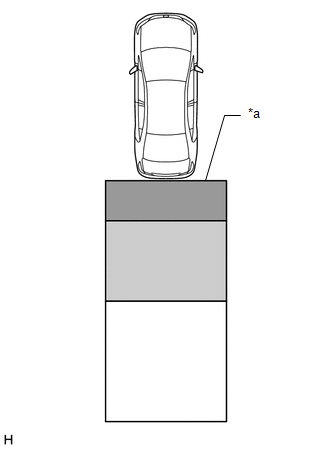
|
*a |
Detection Area |

|
Detection Area A |

|
Detection Area B |

|
Detection Area C |
|
Detection Area |
Buzzer Operation |
Pedestrian Detection Icon |
|---|---|---|
|
A |
Sounds repeatedly |
Blinks 3 times and then stays on |
|
B |
|
|
|
C |
When it is determined that a pedestrian will enter area A within a few seconds: Sounds repeatedly |
When it is determined that a pedestrian will enter area A within a few seconds: Blinks 3 times and then stays on |
HINT:
-
Absolute Detection Area (3.0 m (9.8 ft.) from the edge of bumper, 3.0 m (9.8 ft.) wide
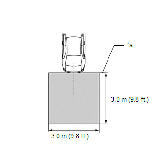
*a
Edge of Bumper
Absolute Detection Area
-
Absolute No Detection Area (4.1 m (13.4 ft.) from the edge of the bumper, 7.2 m (23.6 ft.) wide)
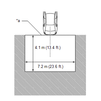
*a
Edge of Bumper

Absolute No Detection Area
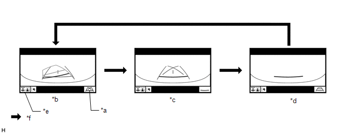
DISPLAY MODE
(a) Rear view screen
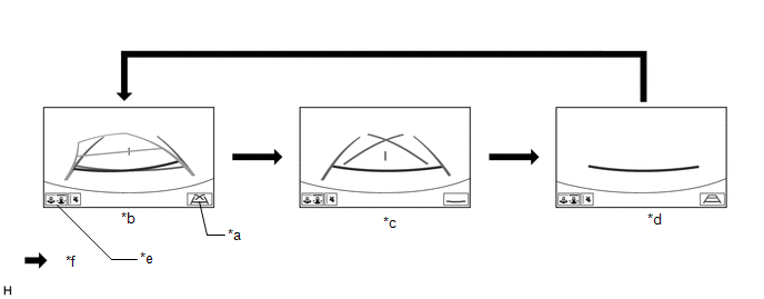
|
*a |
Guide Line Display Mode Switching Button |
*b |
Estimated Course Line Display Mode |
|
*c |
Parking Assist Guide Line Display Mode |
*d |
Distance Guide Line Display Mode |
|
*e |
Display Mode Switching Button |
*f |
Guide Line Display Mode Switching Button Pressed |
HINT:
The screen changes to the wide rear view screen when the display mode switching button is selected.
(1) While the parking assist monitor is displayed on the multi-display, pressing the guide line display mode switching button switches the parking assist monitor display mode.
Parking Assist Monitor Display Mode
|
Parking Assist Monitor Display Mode |
Distance Guide Lines (Red) |
Estimated Course Lines (Yellow) |
Distance Guide Line (Yellow) |
Vehicle Width Extension Guide Line (Blue) |
Distance Guide Line (Blue) |
Parking Assist Guide Lines (Blue) |
Vehicle Center Line (Blue) |
|---|---|---|---|---|---|---|---|
|
Estimated course line display mode |
Displayed |
Displayed |
Displayed |
Displayed |
Displayed |
Not displayed |
Displayed |
|
Parking assist guide line display mode |
Displayed |
Not displayed |
Not displayed |
Displayed |
Not displayed |
Displayed |
Displayed |
|
Distance guide line display mode |
Displayed |
Not displayed |
Not displayed |
Not displayed |
Not displayed |
Not displayed |
Not displayed |
(b) Wide rear view screen
|
*a |
Guide Line Display Mode Switching Button |
*b |
Estimated Course Line Display Mode |
|
*c |
Parking Assist Guide Line Display Mode |
*d |
Distance Guide Line Display Mode |
|
*e |
Display Mode Switching Button |
*f |
Guide Line Display Mode Switching Button Pressed |
HINT:
The screen changes to the rear view screen when the display mode switching button is selected.
(1) While the parking assist monitor is displayed on the multi-display, pressing the guide line display mode switching button switches the parking assist monitor display mode.
Parking Assist Monitor Display Mode
|
Parking Assist Monitor Display Mode |
Distance Guide Lines (Red) |
Estimated Course Lines (Yellow) |
Distance Guide Line (Yellow) |
Vehicle Width Extension Guide Line (Blue) |
Distance Guide Line (Blue) |
Parking Assist Guide Lines (Blue) |
Vehicle Center Line (Blue) |
|---|---|---|---|---|---|---|---|
|
Estimated course line display mode |
Displayed |
Displayed |
Displayed |
Displayed |
Displayed |
Not displayed |
Displayed |
|
Parking assist guide line display mode |
Displayed |
Not displayed |
Not displayed |
Displayed |
Not displayed |
Displayed |
Displayed |
|
Distance guide line display mode |
Displayed |
Not displayed |
Not displayed |
Not displayed |
Not displayed |
Not displayed |
Not displayed |
(c) Rear camera detection function screen
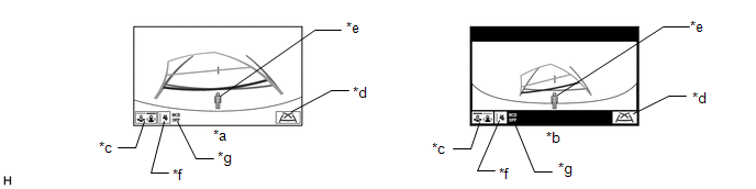
|
*a |
Rear view screen |
*b |
Wide rear view screen |
|
*c |
Display Mode Switching Button |
*d |
Guide Line Display Mode Switching Button |
|
*e |
Pedestrian Detection Icon |
*f |
Mute Switch |
|
*g |
RCD OFF Indicator (Displays Only when Rear Camera Detection is OFF)* |
- |
- |
-
*: The setting can be changed on the diagnosis screen.
Click here
![2018 - 2024 MY Camry HV [07/2017 - ]; PARK ASSIST / MONITORING: PARKING ASSIST MONITOR SYSTEM: DIAGNOSIS SYSTEM](/t3Portal/stylegraphics/info.gif)
DIAGNOSTIC FUNCTION OUTLINE
(a) This parking assist monitor system has a diagnostic function displayed on the multi-display. This function enables calibration (adjustment and verification) of the parking assist monitor system.
Click here
(b) The following items for the parking assist monitor system can be checked using the Techstream.
|
Item |
Proceed to |
|---|---|
|
DTC |
|
|
Data List / Active Test |
|
|
|
|