| Last Modified: 02-14-2025 | 6.11:8.1.0 | Doc ID: RM10000000157CA |
| Model Year Start: 2018 | Model: Camry HV | Prod Date Range: [07/2017 - ] |
| Title: LIGHTING (EXT): LIGHTING SYSTEM (w/ AFS): Taillight Relay Circuit; 2018 - 2024 MY Camry HV [07/2017 - ] | ||
|
Taillight Relay Circuit |
DESCRIPTION
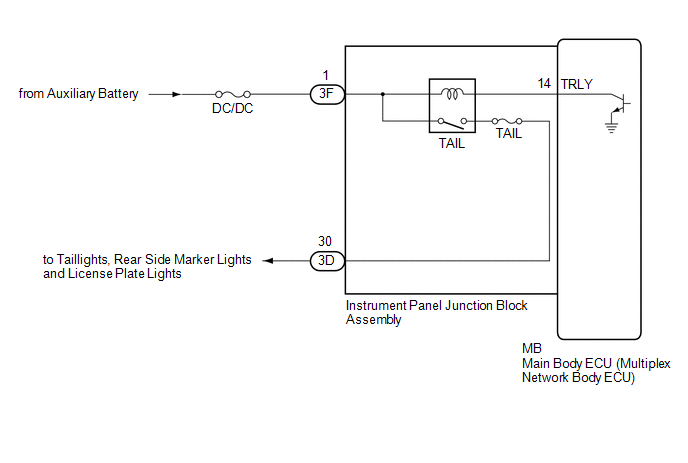
The main body ECU (multiplex network body ECU) controls the operation of the TAIL relay.
WIRING DIAGRAM
CAUTION / NOTICE / HINT
NOTICE:
- Inspect the fuses for circuits related to this system before performing the following procedure.
-
Before replacing the main body ECU (multiplex network body ECU), refer to Registration.
Click here
![2018 - 2019 MY Camry HV [07/2017 - 09/2019]; THEFT DETERRENT / KEYLESS ENTRY: SMART KEY SYSTEM (for Start Function): REGISTRATION](/t3Portal/stylegraphics/info.gif)
PROCEDURE
|
1. |
PERFORM ACTIVE TEST USING TECHSTREAM |
(a) Connect the Techstream to the DLC3.
(b) Turn the power switch on (IG).
(c) Turn the Techstream on.
(d) Enter the following menus: Body Electrical / Main Body / Active Test.
(e) Perform the Active Test according to the display on the Techstream.
Body Electrical > Main Body > Active Test
|
Tester Display |
Measurement Item |
Control Range |
Diagnostic Note |
|---|---|---|---|
|
Taillight Relay |
Taillight relay |
OFF or ON |
- |
Body Electrical > Main Body > Active Test
|
Tester Display |
|---|
|
Taillight Relay |
OK:
Taillights illuminate.
| OK |

|
PROCEED TO NEXT SUSPECTED AREA SHOWN IN PROBLEM SYMPTOMS TABLE
|
|

|
2. |
CHECK HARNESS AND CONNECTOR (POWER SOURCE - INSTRUMENT PANEL JUNCTION BLOCK ASSEMBLY) |
(a) Disconnect the 3F instrument panel junction block assembly connector.
(b) Measure the voltage according to the value(s) in the table below.
Standard Voltage:
|
Tester Connection |
Condition |
Specified Condition |
|---|---|---|
|
3F-1 - Body ground |
Power switch off |
11 to 14 V |
| NG |
|
REPAIR OR REPLACE HARNESS OR CONNECTOR |
|
|
3. |
INSPECT INSTRUMENT PANEL JUNCTION BLOCK ASSEMBLY |
|
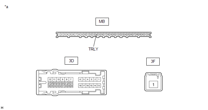
*a |
Component without harness connected (Instrument Panel Junction Block Assembly) |
- |
- |
(a) Remove the instrument panel junction block assembly.
Click here
(b) Remove the main body ECU (multiplex network body ECU) from the instrument panel junction block assembly.
(c) Connect a positive (+) lead from the auxiliary battery to terminal 3F-1.
(d) Connect a negative (-) lead from the auxiliary battery to terminal MB-14 (TRLY).
(e) Measure the voltage according to the value(s) in the table below.
Standard Voltage:
|
Tester Connection |
Condition |
Specified Condition |
|---|---|---|
|
3D-30 - Auxiliary battery negative (-) terminal |
Always |
11 to 14 V |
| OK |
|
REPLACE MAIN BODY ECU (MULTIPLEX NETWORK BODY ECU)
|
| NG |
|
REPLACE INSTRUMENT PANEL JUNCTION BLOCK ASSEMBLY
|
|
|
|