- Side television camera assembly LH
- Side television camera assembly RH
| Last Modified: 02-14-2025 | 6.11:8.1.0 | Doc ID: RM1000000015652 |
| Model Year Start: 2018 | Model: Camry HV | Prod Date Range: [07/2017 - 10/2020] |
| Title: MIRROR (EXT): OUTER REAR VIEW MIRROR COVER: REMOVAL; 2018 - 2020 MY Camry HV [07/2017 - 10/2020] | ||
REMOVAL
CAUTION / NOTICE / HINT
The necessary procedures (adjustment, calibration, initialization, or registration) that must be performed after parts are removed and installed, or replaced during outer rear view mirror assembly with cover removal/installation are shown below.
Necessary Procedure After Parts Removed/Installed/Replaced
|
Replaced Part or Performed Procedure |
Necessary Procedure |
Effect/Inoperative Function when Necessary Procedure not Performed |
Link |
|---|---|---|---|
|
|
Side television camera view adjustment |
Panoramic view monitor system |
|
HINT:
- Use the same procedure for the RH side and LH side.
- The following procedure is for the LH side.
PROCEDURE
1. REMOVE OUTER MIRROR (for Type A)
Click here
![2018 - 2024 MY Camry HV [07/2017 - ]; MIRROR (EXT): OUTER REAR VIEW MIRROR GLASS: REMOVAL+](/t3Portal/stylegraphics/info.gif)
2. REMOVE OUTER MIRROR COVER WITH OUTER MIRROR HOLE COVER (for Type A)
(a) w/o Panoramic View Monitor System:

|
Place Hand Here |

|
Pull in this Direction |
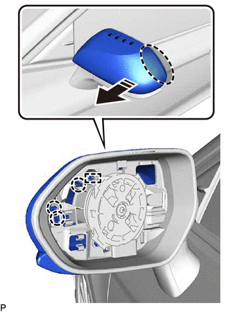
(1) Pull the outer mirror cover with outer mirror hole cover as shown in the illustration to disengage the 3 claws and guide.
NOTICE:
As the claws and guide may be damaged, make sure not to apply force in any direction other than shown in the illustration.
HINT:
If it is difficult to disengage the claws, disengage them using a screwdriver with its tip wrapped with protective tape.
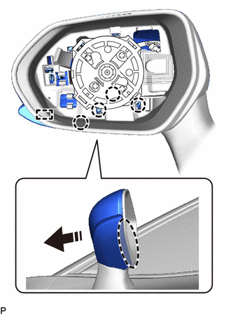
(2) Pull the outer mirror cover with outer mirror hole cover as shown in the illustration to disengage the 4 claws and guide.
NOTICE:
As the claws and guide may be damaged, make sure not to apply force in any direction other than shown in the illustration.
HINT:
If it is difficult to disengage the claws, disengage them using a screwdriver with its tip wrapped with protective tape.

|
|
Place Hand Here |
|
|
Pull in this Direction |
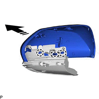
(3) Pull the outer mirror cover with outer mirror hole cover as shown in the illustration to disengage the 4 claws and guide and remove the outer mirror cover with outer mirror hole cover.
NOTICE:
As the claws and guides may be damaged, make sure not to apply force in any direction other than shown in the illustration.
HINT:
If it is difficult to disengage the claws, disengage them using a screwdriver with its tip wrapped with protective tape.
|
|
Place Hand Here |
|
|
Remove in this Direction |
3. REMOVE OUTER MIRROR COVER (for Type A)
(a) w/o Panoramic View Monitor System:
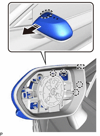
(1) Disengage the 2 claws and guide to remove the outer mirror cover as shown in the illustration.
|
|
Remove in this Direction |
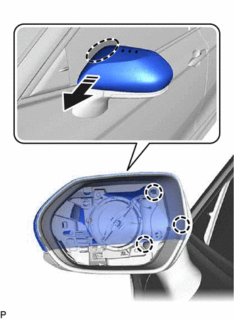
(b) w/ Panoramic View Monitor System:
(1) Pull the outer mirror cover as shown in the illustration to disengage the 3 claws and guide.

|
|
Place Hand Here |
|
|
Pull in this Direction |
NOTICE:
As the claws and guide may be damaged, make sure not to apply force in any direction other than shown in the illustration.
HINT:
If it is difficult to disengage the claws, disengage them using a screwdriver with its tip wrapped with protective tape.
(2) Pull the outer mirror cover as shown in the illustration to disengage the 4 claws and guide.
NOTICE:
As the claws and guide may be damaged, make sure not to apply force in any direction other than shown in the illustration.
HINT:
If it is difficult to disengage the claws, disengage them using a screwdriver with its tip wrapped with protective tape.
|
|
Place Hand Here |
|
|
Pull in this Direction |
(3) Pull the outer mirror cover as shown in the illustration to disengage the 4 claws and guide.

|
|
Place Hand Here |
|
|
Remove in this Direction |
NOTICE:
As the claws and guides may be damaged, make sure not to apply force in any direction other than shown in the illustration.
HINT:
If it is difficult to disengage the claws, disengage them using a screwdriver with its tip wrapped with protective tape.
|
(4) Disengage the 2 claws and guide to remove the outer mirror cover as shown in the illustration. |
|
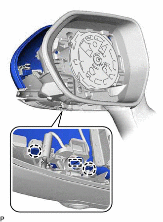
4. REMOVE OUTER MIRROR HOLE COVER WITH SIDE TELEVISION CAMERA ASSEMBLY (for Type A)
(a) w/ Panoramic View Monitor System:
|
(1) Disengage the clamp. |
|
|
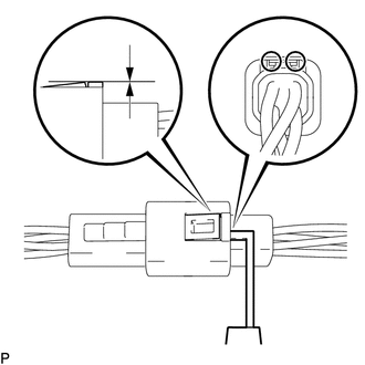
(2) Insert a 0.9 mm (0.0354 in.) spark plug gap gauge or similar tool into the connector as shown in the illustration. NOTICE:
|
|
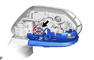
(3) Lift the claw and disconnect the connector to remove the outer mirror hole cover with side television camera assembly.
5. REMOVE SIDE TELEVISION CAMERA ASSEMBLY (for Type A)
w/ Panoramic View Monitor System:
Click here
6. REMOVE OUTER MIRROR (for Type B)
Click here
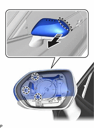
7. REMOVE OUTER MIRROR COVER (for Type B)
(a) Pull the outer mirror cover as shown in the illustration to disengage the 3 claws.
|
|
Place Hand Here |
|
|
Pull in this Direction |
NOTICE:
As the claws may be damaged, make sure not to apply force in any direction other than shown in the illustration.
HINT:
If it is difficult to disengage the claws, disengage them using a screwdriver with its tip wrapped with protective tape.
(b) Pull the outer mirror cover as shown in the illustration to disengage the 3 claws and remove the outer mirror cover.
|
|
Place Hand Here |
|
|
Pull in this Direction |
NOTICE:
As the claws may be damaged, make sure not to apply force in any direction other than shown in the illustration.
HINT:
If it is difficult to disengage the claws, disengage them using a screwdriver with its tip wrapped with protective tape.
|
|
|