| Last Modified: 02-14-2025 | 6.11:8.1.0 | Doc ID: RM100000001543G |
| Model Year Start: 2018 | Model: Camry HV | Prod Date Range: [07/2017 - ] |
| Title: HYBRID / BATTERY CONTROL: HYBRID CONTROL SYSTEM (for NICKEL METAL HYDRIDE BATTERY): Indicator Circuit; 2018 - 2024 MY Camry HV [07/2017 - ] | ||
|
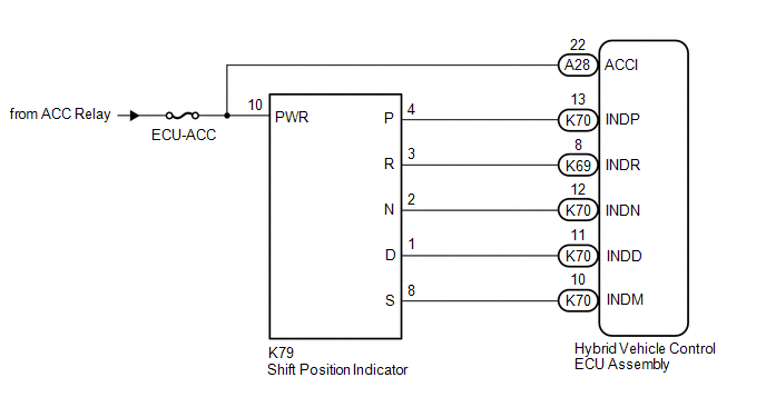
Indicator Circuit |
DESCRIPTION
In accordance with the shift lever position, each shift position indicator light will turn on.
WIRING DIAGRAM
PROCEDURE
|
1. |
CHECK SHIFT POSITION INDICATOR |
(a) Turn the power switch on (ACC).
(b) Check that each shift position indicator light turns on correctly.
|
Result |
Proceed to |
|---|---|
|
All shift position indicator lights turn on simultaneously |
A |
|
Shift position indicator lights other than corresponding one turn on |
B |
|
Corresponding shift position indicator light does not turn on |
C |
|
No shift position indicator lights turn on |
D |
(c) Turn the power switch off.
| B |

|
| C |
|
| D |
|
|

|
2. |
CHECK HARNESS AND CONNECTOR (CHECK FOR SHORT TO GND) |
(a) Disconnect the K69 and K70 hybrid vehicle control ECU assembly connector.
|
(b) Measure the resistance according to the value(s) in the table below. Standard Resistance:
|
|
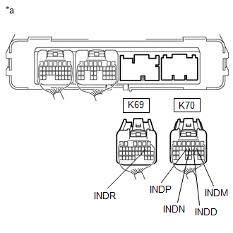
(c) Reconnect the K69 and K70 hybrid vehicle control ECU assembly connector.
| OK |
|
REPLACE HYBRID VEHICLE CONTROL ECU ASSEMBLY
|
![2018 - 2020 MY Camry HV [07/2017 - 10/2020]; HYBRID / BATTERY CONTROL: HYBRID VEHICLE CONTROL ECU: REMOVAL](/t3Portal/stylegraphics/info.gif)
|
|
3. |
CHECK HARNESS AND CONNECTOR (HYBRID VEHICLE CONTROL ECU ASSEMBLY - SHIFT POSITION INDICATOR) |
(a) Disconnect the K69 and K70 hybrid vehicle control ECU assembly connector.
(b) Disconnect the K79 shift position indicator connector.
|
(c) Measure the resistance according to the value(s) in the table below. Standard Resistance:
|
|
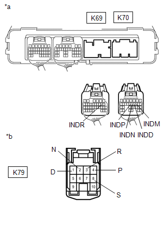
(d) Reconnect the K79 shift position indicator connector.
(e) Reconnect the K69 and K70 hybrid vehicle control ECU assembly connector.
| OK |
|
| NG |
|
REPAIR OR REPLACE HARNESS OR CONNECTOR |
|
4. |
CHECK HARNESS AND CONNECTOR (POWER SOURCE CIRCUIT) |
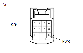
(a) Disconnect the K79 shift position indicator connector.
(b) Turn the power switch on (ACC).
|
(c) Measure the voltage according to the value(s) in the table below. Standard Voltage:
|
|
(d) Turn the power switch off.
(e) Reconnect the K79 shift position indicator connector.
| NG |
|
REPAIR OR REPLACE POWER SOURCE CIRCUIT |
|
|
5. |
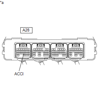
CHECK HARNESS AND CONNECTOR (POWER SOURCE TERMINAL ACCI) |
(a) Turn the power switch on (ACC).
|
(b) Measure the voltage according to the value(s) in the table below. Standard Voltage:
|
|
(c) Turn the power switch off.
| NG |
|
REPAIR OR REPLACE POWER SOURCE CIRCUIT |
|
|
6. |
CHECK HARNESS AND CONNECTOR (CHECK FOR OPEN) |
(a) Disconnect the K69 and K70 hybrid vehicle control ECU assembly connectors.
(b) Turn the power switch on (ACC).
|
(c) Measure the voltage according to the value(s) in the table below. Standard Voltage:
|
|
(d) Turn the power switch off.
(e) Reconnect the K69 and K70 hybrid vehicle control ECU assembly connectors.
| OK |
|
REPLACE HYBRID VEHICLE CONTROL ECU ASSEMBLY
|
|
|
7. |
CHECK HARNESS AND CONNECTOR (HYBRID VEHICLE CONTROL ECU ASSEMBLY - SHIFT POSITION INDICATOR) |
(a) Disconnect the K69 and K70 hybrid vehicle control ECU assembly connectors.
(b) Disconnect the K79 shift position indicator connector.
|
(c) Measure the resistance according to the value(s) in the table below. Standard Resistance:
|
|

(d) Reconnect the K79 shift position indicator connector.
(e) Reconnect the K69 and K70 hybrid vehicle control ECU assembly connectors.
| OK |
|
| NG |
|
REPAIR OR REPLACE HARNESS OR CONNECTOR |
|
|
|