| Last Modified: 02-14-2025 | 6.11:8.1.0 | Doc ID: RM1000000014Y6F |
| Model Year Start: 2018 | Model: Camry HV | Prod Date Range: [07/2017 - 08/2021] |
| Title: POWER OUTLETS (INT): WIRELESS CHARGING SYSTEM: Wireless Charger Illumination Circuit; 2018 - 2021 MY Camry HV [07/2017 - 08/2021] | ||
|
Wireless Charger Illumination Circuit |
DESCRIPTION
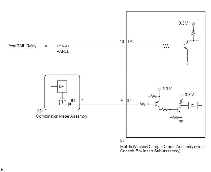
When the light control switch is turned to the tail or head position, this circuit sends an illumination signal to the mobile wireless charger cradle assembly (front console box insert sub-assembly).
WIRING DIAGRAM
CAUTION / NOTICE / HINT
NOTICE:
Inspect the fuses for circuits related to this system before performing the following procedure.
PROCEDURE
|
1. |
CHECK HARNESS AND CONNECTOR (ILLUMINATION SIGNAL) |
(a) Disconnect the k1 mobile wireless charger cradle assembly (front console box insert sub-assembly) connector.
(b) Measure the voltage according to the value(s) in the table below.
Standard Voltage:
|
Tester Connection |
Condition |
Specified Condition |
|---|---|---|
|
k1-10 (TAIL) - Body ground |
Light control switch in off position |
Below 1 V |
|
Power switch off, light control switch in tail or head position |
11 to 14 V |
| NG |

|
REPAIR OR REPLACE HARNESS OR CONNECTOR |
|

|
2. |
CHECK HARNESS AND CONNECTOR (COMBINATION METER ASSEMBLY - MOBILE WIRELESS CHARGER CRADLE ASSEMBLY (FRONT CONSOLE BOX INSERT SUB-ASSEMBLY)) |
(a) Disconnect the K21 combination meter assembly connector.
(b) Measure the resistance according to the value(s) in the table below.
Standard Resistance:
|
Tester Connection |
Condition |
Specified Condition |
|---|---|---|
|
K21-1 (ILL-) - k1-9 (ILL-) |
Always |
Below 1 Ω |
|
K21-1 (ILL-) or k1-9 (ILL-) - Body ground |
Always |
10 kΩ or higher |
| OK |
|
PROCEED TO NEXT SUSPECTED AREA SHOWN IN PROBLEM SYMPTOMS TABLE |
| NG |
|
REPAIR OR REPLACE HARNESS OR CONNECTOR |
|
|
|