| Last Modified: 02-14-2025 | 6.11:8.1.0 | Doc ID: RM1000000014WA6 |
| Model Year Start: 2018 | Model: Camry HV | Prod Date Range: [07/2017 - 10/2020] |
| Title: PRE-COLLISION: PRE-COLLISION SYSTEM: U023A; Lost Communication With Image Processing Module "A"; 2018 - 2020 MY Camry HV [07/2017 - 10/2020] | ||
|
DTC |
U023A |
Lost Communication With Image Processing Module "A" |
DESCRIPTION
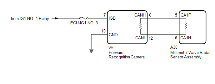
The millimeter wave radar sensor assembly communicates with the forward recognition camera via CAN communication. If there is a communication error with the forward recognition camera, the millimeter wave radar sensor assembly stores DTC U023A.
|
DTC No. |
Detection Item |
DTC Detection Condition |
Trouble Area |
|---|---|---|---|
|
U023A |
Lost Communication With Image Processing Module "A" |
When the power switch is on (IG), a communication error between the forward recognition camera and millimeter wave radar sensor assembly is detected for approximately 2 seconds. |
|
WIRING DIAGRAM
CAUTION / NOTICE / HINT
NOTICE:
- Inspect the fuses for circuits related to this system before performing the following inspection procedure.
- Before measuring the resistance of the CAN bus, turn the power switch off and leave the vehicle for 1 minute or more without operating the key or any switches, or opening or closing the doors. After that, disconnect the cable from the negative (-) auxiliary battery terminal and leave the vehicle for 1 minute or more before measuring the resistance.
-
After turning the power switch off, waiting time may be required before disconnecting the cable from the negative (-) auxiliary battery terminal. Therefore, make sure to read the disconnecting the cable from the negative (-) auxiliary battery terminal notices before proceeding with work.
Click here
![2018 - 2019 MY Camry HV [07/2017 - 09/2019]; INTRODUCTION: REPAIR INSTRUCTION: PRECAUTION](/t3Portal/stylegraphics/info.gif)
- When replacing the forward recognition camera, always replace it with a new one. If a forward recognition camera which was installed to another vehicle is used, the information stored in the forward recognition camera will not match the information from the vehicle. As a result, a DTC may be stored.
-
If the forward recognition camera has been replaced with a new one, be sure to perform forward recognition camera adjustment.
Click here
HINT:
- Before disconnecting related connectors for inspection, push in on each connector body to check that the connector is not loose or disconnected.
- When a connector is disconnected, check that the terminals and connector body are not cracked, deformed or corroded.
PROCEDURE
|
1. |
READ VALUE USING TECHSTREAM (CAN BUS CHECK) |
(a) Connect the Techstream to the DLC3.
(b) Turn the power switch on (IG).
(c) Turn the Techstream on.
(d) Enter the following menus: System Select / Can Bus Check.
CAN Bus Check
|
Result |
Proceed to |
|---|---|
|
All of the ECUs and sensors that are currently connected to the CAN communication system are displayed |
A |
|
None of the ECUs and sensors that are currently connected to the CAN communication system are displayed, or some of them are not displayed |
B |
| B |

|
|

|
2. |
CHECK FOR DTCs (PRE-COLLISION SYSTEM) |
(a) Clear the DTCs.
Body Electrical > Pre-Collision 2 > Clear DTCs
(b) Perform the following procedure.
HINT:
If the following procedure is not performed, the previously output DTC cannot be detected.
- Turn the power switch on (IG) and wait 2 seconds or more.
(c) Check for DTCs.
Body Electrical > Pre-Collision 2 > Trouble Codes
|
Result |
Proceed to |
|---|---|
|
DTC U1002 is not output |
A |
|
DTC U1002 is output |
B |
| B |
|
|
|
3. |
CHECK FOR OPEN IN CAN BUS LINES (MILLIMETER WAVE RADAR SENSOR ASSEMBLY - FORWARD RECOGNITION CAMERA) |
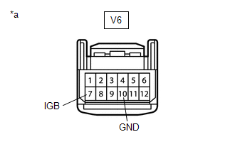
(a) Disconnect the V6 forward recognition camera connector.
(b) Disconnect the A30 millimeter wave radar sensor assembly connector.
(c) Measure the resistance according to the value(s) in the table below.
Standard Resistance:
|
Tester Connection |
Condition |
Specified Condition |
|---|---|---|
|
V6-6 (CANH) - A30-5 (CA1P) |
Cable disconnected from negative (-) auxiliary battery terminal |
Below 1 Ω |
|
V6-12 (CANL) - A30-6 (CA1N) |
Cable disconnected from negative (-) auxiliary battery terminal |
Below 1 Ω |
(d) Connect the A30 millimeter wave radar sensor assembly connector.
(e) Connect the V6 forward recognition camera connector.
| NG |
|
REPAIR OR REPLACE CAN BUS LINE OR CONNECTOR (MILLIMETER WAVE RADAR SENSOR ASSEMBLY - FORWARD RECOGNITION CAMERA) |
|
|
4. |
CHECK HARNESS AND CONNECTOR (POWER SOURCE VOLTAGE) |
|
(a) Disconnect the V6 forward recognition camera connector. |
|
(b) Measure the resistance according to the value(s) in the table below.
Standard Resistance:
|
Tester Connection |
Condition |
Specified Condition |
|---|---|---|
|
V6-10 (GND) - Body ground |
Always |
Below 1 Ω |
(c) Connect the cable to the negative (-) auxiliary battery terminal.
(d) Measure the voltage according to the value(s) in the table below.
Standard Voltage:
|
Tester Connection |
Condition |
Specified Condition |
|---|---|---|
|
V6-7 (IGB) - Body ground |
Power switch on (IG) |
11 to 14 V |
(e) Connect the V6 forward recognition camera connector.
| OK |
|
| NG |
|
REPAIR OR REPLACE HARNESS OR CONNECTOR (POWER SOURCE CIRCUIT) |
|
|
|