| Last Modified: 02-14-2025 | 6.11:8.1.0 | Doc ID: RM1000000014VNH |
| Model Year Start: 2018 | Model: Camry HV | Prod Date Range: [07/2017 - 09/2018] |
| Title: BRAKE CONTROL / DYNAMIC CONTROL SYSTEMS: ELECTRONICALLY CONTROLLED BRAKE SYSTEM: C146E,C146F; Open Circuit in ABS Solenoid Relay Circuit; 2018 MY Camry HV [07/2017 - 09/2018] | ||
|
DTC |
C146E |
Open Circuit in ABS Solenoid Relay Circuit |
|
DTC |
C146F |
Short Circuit in ABS Solenoid Relay Circuit |
DESCRIPTION
The ABS solenoid relay built into the skid control ECU (brake booster with master cylinder assembly) supplies power to the holding solenoid and reduction solenoid.
The ABS solenoid relay is operated 1.5 seconds after the power switch is turned on (IG), and is turned off if an open or short in the ABS solenoid is detected during self-diagnosis when the vehicle starts driving.
|
DTC No. |
Detection Item |
INF Code |
DTC Detection Condition |
Trouble Area |
Note |
|---|---|---|---|---|---|
|
C146E |
Open Circuit in ABS Solenoid Relay Circuit |
1135 |
Either of the following is detected:
|
|
ABS DTC |
|
C146F |
Short Circuit in ABS Solenoid Relay Circuit |
1136 |
When operation of the ABS solenoid relay is not requested, the ABS solenoid relay operates (+BS terminal voltage is 3.5 V or more) for 4.5 seconds or more. |
Skid control ECU (brake booster with master cylinder assembly) |
ABS DTC |
DTC Detection Conditions: C146E INF Code: 1135
|
Vehicle Condition |
|||
|---|---|---|---|
|
Pattern 1 |
Pattern 2 |
||
|
Diagnosis Condition |
The IG1 terminal voltage is 9.5 V or more with the power switch on (READY). |
○ |
- |
|
When the power switch is off. |
- |
○ |
|
|
Malfunction Status |
When operation of the ABS solenoid relay is requested, the ABS solenoid relay does not operate (+BS terminal voltage is less than 3.5 V). |
○ |
- |
|
When operation of the ABS solenoid relay is requested, the ABS solenoid relay does not operate (+BS terminal voltage is less than 3.5 V). |
- |
○ |
|
|
Detection Time |
0.2 seconds or more |
0.2 seconds or more |
|
|
Number of Trips |
1 trip |
1 trip |
|
HINT:
DTC will be output when conditions for either of the patterns in the table above are met.
WIRING DIAGRAM
Refer to DTCs C1352, C1353, C1354, C1355, C1356, C1357, C1358 and C1359.
Click here
![2018 MY Camry HV [07/2017 - 09/2018]; BRAKE CONTROL / DYNAMIC CONTROL SYSTEMS: ELECTRONICALLY CONTROLLED BRAKE SYSTEM: C1352-C1359; Increasing Pressure Solenoid (FR)](/t3Portal/stylegraphics/info.gif)
CAUTION / NOTICE / HINT
NOTICE:
-
After replacing the skid control ECU (brake booster with master cylinder assembly), perform linear solenoid valve offset learning, ABS holding solenoid valve learning, yaw rate and acceleration sensor zero point calibration and system information memorization after performing "Reset Memory".
Click here
- Inspect the fuses for circuits related to this system before performing the following procedure.
HINT:
When DTCs C1241 and/or C1417 are output together with C146E and/or C146F, inspect and repair the trouble areas indicated by C1241 and/or C1417 first.
for C1241: Click here
for C1417: Click here
PROCEDURE
|
1. |
CHECK HARNESS AND CONNECTOR (BS TERMINAL) |
|
(a) Make sure that there is no looseness at the locking part and the connecting part of the connector. OK: The connector is securely connected. |
|
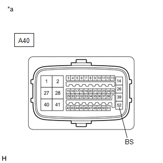
(b) Disconnect the A40 skid control ECU (brake booster with master cylinder assembly) connector.
(c) Check both the connector case and the terminals for deformation and corrosion.
OK:
No deformation or corrosion.
(d) Measure the voltage according to the value(s) in the table below.
Standard Voltage:
|
Tester Connection |
Condition |
Specified Condition |
|---|---|---|
|
A40-52 (BS) - Body ground |
Always |
11 to 14 V |
| NG |

|
REPAIR OR REPLACE HARNESS OR CONNECTOR (BS CIRCUIT) |
|

|
2. |
CHECK HARNESS AND CONNECTOR (BRAKE BOOSTER WITH MASTER CYLINDER ASSEMBLY - BRAKE ACTUATOR ASSEMBLY) |
(a) Make sure that there is no looseness at the locking part and the connecting part of the connector.
OK:
The connector is securely connected.
(b) Disconnect the A44 brake actuator assembly connector.
(c) Check both the connector case and the terminals for deformation and corrosion.
OK:
No deformation or corrosion.
(d) Measure the resistance according to the value(s) in the table below.
Standard Resistance:
|
Tester Connection |
Condition |
Specified Condition |
|---|---|---|
|
A40-14 (+BS) - A44-5 (+BS) |
Always |
Below 1 Ω |
|
A40-14 (+BS) or A44-5 (+BS) - Body ground |
Always |
10 kΩ or higher |
|
A40-48 (SFRH) - A44-28 (SFRH) |
Always |
Below 1 Ω |
|
A40-48 (SFRH) or A44-28 (SFRH) - Body ground |
Always |
10 kΩ or higher |
|
A40-49 (SFLH) - A44-31 (SFLH) |
Always |
Below 1 Ω |
|
A40-49 (SFLH) or A44-31 (SFLH) - Body ground |
Always |
10 kΩ or higher |
|
A40-50 (SRRH) - A44-30 (SRRH) |
Always |
Below 1 Ω |
|
A40-50 (SRRH) or A44-30 (SRRH) - Body ground |
Always |
10 kΩ or higher |
|
A40-51 (SRLH) - A44-29 (SRLH) |
Always |
Below 1 Ω |
|
A40-51 (SRLH) or A44-29 (SRLH) - Body ground |
Always |
10 kΩ or higher |
|
A40-44 (SFRR) - A44-18 (SFRR) |
Always |
Below 1 Ω |
|
A40-44 (SFRR) or A44-18 (SFRR) - Body ground |
Always |
10 kΩ or higher |
|
A40-45 (SFLR) - A44-15 (SFLR) |
Always |
Below 1 Ω |
|
A40-45 (SFLR) or A44-15 (SFLR) - Body ground |
Always |
10 kΩ or higher |
|
A40-46 (SRRR) - A44-16 (SRRR) |
Always |
Below 1 Ω |
|
A40-46 (SRRR) or A44-16 (SRRR) - Body ground |
Always |
10 kΩ or higher |
|
A40-47 (SRLR) - A44-17 (SRLR) |
Always |
Below 1 Ω |
|
A40-47 (SRLR) or A44-17 (SRLR) - Body ground |
Always |
10 kΩ or higher |
| NG |
|
REPAIR OR REPLACE HARNESS OR CONNECTOR |
|
|
3. |
RECONFIRM DTC |
(a) Reconnect the A40 skid control ECU (brake booster with master cylinder assembly) connector.
(b) Reconnect the A44 brake actuator assembly connector.
(c) Clear the DTCs.
Chassis > ABS/VSC/TRAC > Clear DTCs
(d) Turn the power switch off.
(e) Turn the power switch on (READY).
(f) Perform a road test.
(g) Check if the same DTC is output.
Chassis > ABS/VSC/TRAC > Trouble Codes
|
Result |
Proceed to |
|---|---|
|
DTCs C146E and C146F are not output. |
A |
|
DTCs C146E and/or C146F are output. |
B |
HINT:
- If a speed signal of 20 km/h (12 mph) or more is sent to the skid control ECU (brake booster with master cylinder assembly) with the power switch on (IG) and the stop light switch assembly off, the ECU performs self diagnosis of the motor and solenoid circuits.
- If the normal system code is output (no DTCs are output), slightly jiggle the connectors, wire harness, and fuses of the skid control ECU (brake booster with master cylinder assembly).
- If any DTCs are output while jiggling a connector or wire harness from the brake booster with master cylinder assembly, inspect and repair the connector or wire harness.
- The DTCs were probably output due to a bad connection of the connector terminal.
| A |
|
| B |
|
|
|
|