| Last Modified: 02-14-2025 | 6.11:8.1.0 | Doc ID: RM1000000014VN8 |
| Model Year Start: 2018 | Model: Camry HV | Prod Date Range: [07/2017 - 09/2018] |
| Title: BRAKE CONTROL / DYNAMIC CONTROL SYSTEMS: ELECTRONICALLY CONTROLLED BRAKE SYSTEM: C1428; Motor Circuit; 2018 MY Camry HV [07/2017 - 09/2018] | ||
|
DTC |
C1428 |
Motor Circuit |
DESCRIPTION
|
DTC No. |
Detection Item |
INF Code |
DTC Detection Condition |
Trouble Area |
Note |
|---|---|---|---|---|---|
|
C1428 |
Motor Circuit |
611 1160 |
|
Brake actuator assembly |
ABS DTC |
WIRING DIAGRAM
Refer to DTC C1427.
Click here
![2018 MY Camry HV [07/2017 - 09/2018]; BRAKE CONTROL / DYNAMIC CONTROL SYSTEMS: ELECTRONICALLY CONTROLLED BRAKE SYSTEM: C1427; Malfunction in Motor+](/t3Portal/stylegraphics/info.gif)
CAUTION / NOTICE / HINT
NOTICE:
After replacing the brake actuator assembly, perform linear solenoid valve offset learning, ABS holding solenoid valve learning, yaw rate and acceleration sensor zero point calibration and system information memorization after performing "Reset Memory".
Click here
PROCEDURE
|
1. |
CHECK HARNESS AND CONNECTOR (BRAKE BOOSTER WITH MASTER CYLINDER ASSEMBLY - BRAKE ACTUATOR ASSEMBLY) |
(a) Make sure that there is no looseness at the locking part and the connecting part of the connectors.
OK:
The connector is securely connected.
(b) Disconnect the A40 skid control ECU (brake booster with master cylinder assembly) connector.
(c) Disconnect the A44 brake actuator assembly connector.
(d) Check both the connector case and the terminals for deformation and corrosion.
OK:
No deformation or corrosion.
(e) Measure the resistance according to the value(s) in the table below.
Standard Resistance:
|
Tester Connection |
Condition |
Specified Condition |
|---|---|---|
|
A40-40 (+BM) - A44-10 (+BM) |
Always |
Below 1 Ω |
|
A40-40 (+BM) or A44-10 (+BM) - Body ground |
Always |
10 kΩ or higher |
| NG |

|
REPAIR OR REPLACE HARNESS OR CONNECTOR |
|

|
2. |
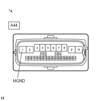
CHECK HARNESS AND CONNECTOR (GND TERMINAL) |
|
(a) Measure the resistance according to the value(s) in the table below. Standard Resistance:
|
|
| OK |
|
| NG |
|
REPAIR OR REPLACE HARNESS OR CONNECTOR (GND CIRCUIT) |
|
|
|