
- Power switch on (IG)
- The headlights are on
- The blower motor switch is in the HI position
- The rear window defogger is turned on
- Stop light switch assembly off (Brake pedal released)
| Last Modified: 02-14-2025 | 6.11:8.1.0 | Doc ID: RM1000000014VN6 |
| Model Year Start: 2018 | Model: Camry HV | Prod Date Range: [07/2017 - 09/2018] |
| Title: BRAKE CONTROL / DYNAMIC CONTROL SYSTEMS: ELECTRONICALLY CONTROLLED BRAKE SYSTEM: C1425; Open in Stop Switch Circuit; 2018 MY Camry HV [07/2017 - 09/2018] | ||
|
DTC |
C1425 |
Open in Stop Switch Circuit |
DESCRIPTION
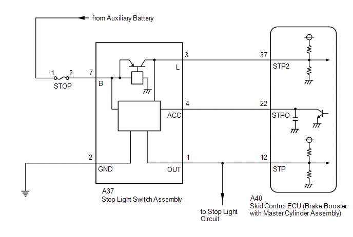
The skid control ECU (brake booster with master cylinder assembly) detects the brake operating conditions through a signal transmitted by the stop light switch assembly.
The skid control ECU incorporates a circuit to detect an open circuit. This DTC is output when an open circuit is detected in the stop light signal input line.
|
DTC No. |
Detection Item |
INF Code |
DTC Detection Condition |
Trouble Area |
Note |
|---|---|---|---|---|---|
|
C1425 |
Open in Stop Switch Circuit |
231 |
An open stop light switch circuit continues for 10 seconds or more. |
|
Electronically controlled brake system DTC |
WIRING DIAGRAM
CAUTION / NOTICE / HINT
NOTICE:
-
After replacing the skid control ECU (brake booster with master cylinder assembly), perform linear solenoid valve offset learning, ABS holding solenoid valve learning, yaw rate and acceleration sensor zero point calibration and system information memorization after performing "Reset Memory".
Click here
![2018 MY Camry HV [07/2017 - 09/2018]; BRAKE CONTROL / DYNAMIC CONTROL SYSTEMS: ELECTRONICALLY CONTROLLED BRAKE SYSTEM: INITIALIZATION](/t3Portal/stylegraphics/info.gif)
- Inspect the fuses for circuits related to this system before performing the following procedure.
PROCEDURE
|
1. |
CHECK STOP LIGHT OPERATION |
(a) Check that the stop lights come on when the brake pedal is depressed.
|
Result |
Proceed to |
|---|---|
|
All stop lights illuminate when the brake pedal is depressed and turn off when the brake pedal is released. |
A |
|
All stop lights do not illuminate when the brake pedal is depressed. |
B |
|
One or more stop lights illuminate when the brake pedal is depressed but remain on when the brake pedal is released. |
C |
| B |

|
| C |
|
|
|
2. |
READ VALUE USING TECHSTREAM (STOP LIGHT SWITCH ASSEMBLY) |
(a) Select the Data List on the Techstream.
Chassis > ABS/VSC/TRAC > Data List
|
Tester Display |
Measurement Item |
Range |
Normal Condition |
Diagnostic Note |
|---|---|---|---|---|
|
Stop Light SW |
Stop light switch assembly |
ON or OFF |
ON: Brake pedal depressed OFF: Brake pedal released |
- |
Chassis > ABS/VSC/TRAC > Data List
|
Tester Display |
|---|
|
Stop Light SW |
(b) Check the value of Stop Light SW when the brake pedal is depressed.
|
Result |
Proceed to |
|---|---|
|
The value of Stop Light SW is ON. |
A |
|
Other than above. |
B |
| B |
|
|
|
3. |
STOP LIGHT SWITCH ASSEMBLY OUTPUT CIRCUIT INSPECTION |
|
(a) Turn the power switch off. |
|
(b) Make sure that there is no looseness at the locking part and the connecting part of the connector.
OK:
The connector is securely connected.
(c) Measure the voltage according to the value(s) in the table below.
Standard Voltage:
|
Tester Connection |
Condition |
Specified Condition |
|---|---|---|
|
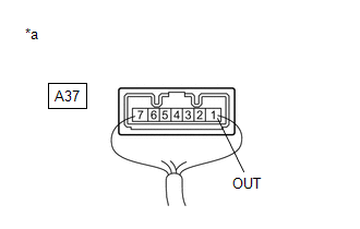
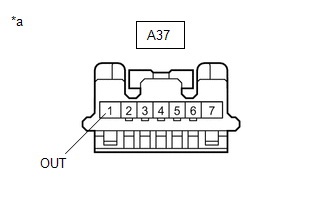
A37-1 (OUT) - Body ground |
|
1.5 V or less |
| NG |
|
|
|
4. |
CLEAR DTC |
(a) Clear the DTCs.
Chassis > ABS/VSC/TRAC > Clear DTCs
|
|
5. |
RECONFIRM DTC |
(a) Turn the power switch off.
(b) Turn the power switch on (READY).
(c) Perform a road test.
(d) Check if the same DTC is output.
Chassis > ABS/VSC/TRAC > Trouble Codes
|
Result |
Proceed to |
|---|---|
|
DTC C1425 is not output. |
A |
|
DTC C1425 is output. |
B |
| A |
|
| B |
|
|
6. |
CHECK STOP LIGHT SWITCH ASSEMBLY |
(a) Turn the power switch off.
(b) Make sure that there is no looseness at the locking part and the connecting part of the connector.
OK:
The connector is securely connected.
|
(c) Disconnect the A37 stop light switch assembly connector. |
|
(d) Check both the connector case and the terminals for deformation and corrosion.
OK:
No deformation or corrosion.
(e) Measure the voltage according to the value(s) in the table below.
Standard Voltage:
|
Tester Connection |
Condition |
Specified Condition |
|---|---|---|
|
A37-1 (OUT) - Body ground |
Stop light switch assembly off (Brake pedal released) |
1.5 V or less |
| OK |
|
|
|
7. |
CHECK BRAKE BOOSTER WITH MASTER CYLINDER ASSEMBLY |
(a) Make sure that there is no looseness at the locking part and the connecting part of the connector.
OK:
The connector is securely connected.
|
(b) Disconnect the A40 skid control ECU (brake booster with master cylinder assembly) connector. |
|
(c) Check both the connector case and the terminals for deformation and corrosion.
OK:
No deformation or corrosion.
(d) Measure the voltage according to the value(s) in the table below.
Standard Voltage:
|
Tester Connection |
Condition |
Specified Condition |
|---|---|---|
|
A37-1 (OUT) - Body ground |
Stop light switch assembly off (Brake pedal released) |
1.5 V or less |
| OK |
|
|
|
8. |
CHECK FOR SHORT TO +B IN STP CIRCUIT |
(a) Check that there is no short to +B in the STP circuit (wire harnesses, connectors and stop lights).
OK:
No short to +B.
| OK |
|
| NG |
|
REPAIR OR REPLACE MALFUNCTIONING PART |
|
9. |
CHECK HARNESS AND CONNECTOR (STP TERMINAL) |
|
(a) Turn the power switch off. |
|
(b) Make sure that there is no looseness at the locking part and the connecting part of the connector.
OK:
The connector is securely connected.
(c) Disconnect the A40 skid control ECU (brake booster with master cylinder assembly) connector.
(d) Check both the connector case and the terminals for deformation and corrosion.
OK:
No deformation or corrosion.
(e) Measure the voltage according to the value(s) in the table below.
Standard Voltage:
|
Tester Connection |
Condition |
Specified Condition |
|---|---|---|
|
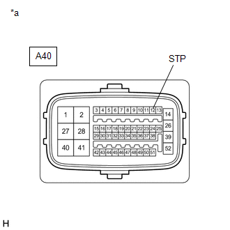
A40-12 (STP) - Body ground |
Stop light switch assembly on (Brake pedal depressed) |
11 to 14 V |
| OK |
|
| NG |
|
REPAIR OR REPLACE HARNESS OR CONNECTOR (STP CIRCUIT) |
|
10. |
CHECK HARNESS AND CONNECTOR (STOP LIGHT SWITCH ASSEMBLY - STOP LIGHT) |
(a) Check that there is no open in the wire harnesses and connectors from terminal OUT of the stop light switch assembly to the stop lights.
OK:
No open.
| OK |
|
| NG |
|
REPAIR OR REPLACE HARNESS OR CONNECTOR |
|
|
|