| Last Modified: 02-14-2025 | 6.11:8.1.0 | Doc ID: RM1000000014VMZ |
| Model Year Start: 2018 | Model: Camry HV | Prod Date Range: [07/2017 - 09/2018] |
| Title: BRAKE CONTROL / DYNAMIC CONTROL SYSTEMS: ELECTRONICALLY CONTROLLED BRAKE SYSTEM: C1403,C1404; Malfunction in Rear Speed Sensor RH Circuit; 2018 MY Camry HV [07/2017 - 09/2018] | ||
|
DTC |
C1403 |
Malfunction in Rear Speed Sensor RH Circuit |
|
DTC |
C1404 |
Malfunction in Rear Speed Sensor LH Circuit |
DESCRIPTION
Refer to DTCs C1415 and C1416.
Click here
![2018 MY Camry HV [07/2017 - 09/2018]; BRAKE CONTROL / DYNAMIC CONTROL SYSTEMS: ELECTRONICALLY CONTROLLED BRAKE SYSTEM: C1415,C1416; Rear Speed Sensor RH Circuit Output](/t3Portal/stylegraphics/info.gif)
|
DTC No. |
Detection Item |
INF Code |
DTC Detection Condition |
Trouble Area |
Note |
|---|---|---|---|---|---|
|
C1403 |
Malfunction in Rear Speed Sensor RH Circuit |
521 522 527 |
|
|
ABS DTC |
|
C1404 |
Malfunction in Rear Speed Sensor LH Circuit |
531 532 537 |
|
|
ABS DTC |
WIRING DIAGRAM
Refer to DTCs C1415 and C1416.
Click here
PROCEDURE
|
1. |
CHECK DTC |
(a) Clear the DTCs.
Chassis > ABS/VSC/TRAC > Clear DTCs
(b) Turn the power switch off.
(c) Turn the power switch on (IG).
(d) Check if the same DTC is output.
Chassis > ABS/VSC/TRAC > Trouble Codes
|
Result |
Proceed to |
|---|---|
|
DTC C1403 is output. |
A |
|
DTC C1404 is output. |
B |
| B |

|
|

|
2. |
CHECK REAR SPEED SENSOR RH INSTALLATION |
|
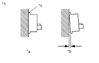
(a) Check the rear speed sensor RH installation. OK: There is no clearance between the sensor and the rear axle hub. HINT: Because the rear axle hub and bearing assembly RH cannot be disassembled, if the rear speed sensor RH needs replacement, replace the rear axle hub and bearing assembly RH. |
|
| NG |
|
|
|
3. |
READ VALUE USING TECHSTREAM (REAR SPEED SENSOR RH) |
(a) Select the Data List on the Techstream.
Chassis > ABS/VSC/TRAC > Data List
|
Tester Display |
Measurement Item |
Range |
Normal Condition |
Diagnostic Note |
|---|---|---|---|---|
|
RR Wheel Speed |
Rear speed sensor RH |
Min.: 0 km/h (0 mph), Max.: 326.4 km/h (203 mph) |
Vehicle stopped: 0 km/h (0 mph) |
When driving at constant speed: No large fluctuations |
Chassis > ABS/VSC/TRAC > Data List
|
Tester Display |
|---|
|
RR Wheel Speed |
(b) Check the rear speed sensor RH output value.
OK:
The output value changes in accordance with the vehicle speed.
| OK |
|
|
|
4. |
INSPECT NO. 1 PARKING BRAKE WIRE ASSEMBLY |
|
(a) Turn the power switch off. |
|
(b) Make sure that there is no looseness at the locking part and the connecting part of the connectors.
OK:
The connector is securely connected.
(c) Remove the skid control sensor wire RH (NO. 1 parking brake wire assembly).
(d) Check both the connector case and the terminals for deformation and corrosion.
OK:
No deformation or corrosion.
(e) Measure the resistance according to the value(s) in the table below.
Standard Resistance:
|
Tester Connection |
Condition |
Specified Condition |
|---|---|---|
|
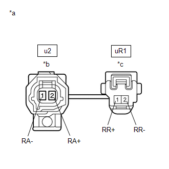
u2-2 (RA+) - uR1-1 (RR+) |
Always |
Below 1 Ω |
|
u2-2 (RA+) - uR1-2 (RR-) |
Always |
10 kΩ or higher |
|
u2-2 (RA+) or uR1-1 (RR+) - Body ground |
Always |
10 kΩ or higher |
|
u2-1 (RA-) - uR1-2 (RR-) |
Always |
Below 1 Ω |
|
u2-1 (RA-) - uR1-1 (RR+) |
Always |
10 kΩ or higher |
|
u2-1 (RA-) or uR1-2 (RR-) - Body ground |
Always |
10 kΩ or higher |
| NG |
|
REPLACE NO. 1 PARKING BRAKE WIRE ASSEMBLY |
|
|
5. |
CHECK HARNESS AND CONNECTOR (BRAKE BOOSTER WITH MASTER CYLINDER ASSEMBLY - NO. 1 PARKING BRAKE WIRE ASSEMBLY) |
(a) Make sure that there is no looseness at the locking part and the connecting part of the connector.
OK:
The connector is securely connected.
(b) Disconnect the A40 skid control ECU (brake booster with master cylinder assembly) connector.
(c) Check both the connector case and the terminals for deformation and corrosion.
OK:
No deformation or corrosion.
(d) Measure the resistance according to the value(s) in the table below.
Standard Resistance:
|
Tester Connection |
Condition |
Specified Condition |
|---|---|---|
|
A40-7 (RR+) - uR1-1 (RR+) |
Always |
Below 1 Ω |
|
A40-7 (RR+) or uR1-1 (RR+) - Body ground |
Always |
10 kΩ or higher |
|
A40-8 (RR-) - uR1-2 (RR-) |
Always |
Below 1 Ω |
|
A40-8 (RR-) or uR1-2 (RR-) - Body ground |
Always |
10 kΩ or higher |
NOTICE:
Check the rear speed sensor RH signal after replacement.
Click here
HINT:
The rear speed sensor RH and rear speed sensor rotor RH are incorporated into the rear axle hub and bearing assembly RH.
If the rear speed sensor RH and rear speed sensor rotor RH need to be replaced, replace the rear axle hub and bearing assembly RH.
| OK |
|
| NG |
|
REPAIR OR REPLACE HARNESS OR CONNECTOR |
|
6. |
CHECK REAR SPEED SENSOR LH INSTALLATION |
|
(a) Check the rear speed sensor LH installation. OK: There is no clearance between the sensor and the rear axle hub. HINT: Because the rear axle hub and bearing assembly LH cannot be disassembled, if the rear speed sensor LH needs replacement, replace the rear axle hub and bearing assembly LH. |
|
| NG |
|
|
|
7. |
READ VALUE USING TECHSTREAM (REAR SPEED SENSOR LH) |
(a) Select the Data List on the Techstream.
Chassis > ABS/VSC/TRAC > Data List
|
Tester Display |
Measurement Item |
Range |
Normal Condition |
Diagnostic Note |
|---|---|---|---|---|
|
RL Wheel Speed |
Rear speed sensor LH |
Min.: 0 km/h (0 mph), Max.: 326.4 km/h (203 mph) |
Vehicle stopped: 0 km/h (0 mph) |
When driving at constant speed: No large fluctuations |
Chassis > ABS/VSC/TRAC > Data List
|
Tester Display |
|---|
|
RL Wheel Speed |
(b) Check the rear speed sensor LH output value.
OK:
The output value changes in accordance with the vehicle speed.
| OK |
|
|
|
8. |
INSPECT NO. 2 PARKING BRAKE WIRE ASSEMBLY |
|
(a) Turn the power switch off. |
|
(b) Make sure that there is no looseness at the locking part and the connecting part of the connectors.
OK:
The connector is securely connected.
(c) Remove the skid control sensor wire LH (NO. 2 parking brake wire assembly).
(d) Check both the connector case and the terminals for deformation and corrosion.
OK:
No deformation or corrosion.
(e) Measure the resistance according to the value(s) in the table below.
Standard Resistance:
|
Tester Connection |
Condition |
Specified Condition |
|---|---|---|
|
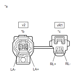
v2-2 (LA+) - vR1-1 (RL+) |
Always |
Below 1 Ω |
|
v2-2 (LA+) - vR1-2 (RL-) |
Always |
10 kΩ or higher |
|
v2-2 (LA+) or vR1-1 (RL+) - Body ground |
Always |
10 kΩ or higher |
|
v2-1 (LA-) - vR1-2 (RL-) |
Always |
Below 1 Ω |
|
v2-1 (LA-) - vR1-1 (RL+) |
Always |
10 kΩ or higher |
|
v2-1 (LA-) or vR1-2 (RL-) - Body ground |
Always |
10 kΩ or higher |
| NG |
|
REPLACE NO. 2 PARKING BRAKE WIRE ASSEMBLY |
|
|
9. |
CHECK HARNESS AND CONNECTOR (BRAKE BOOSTER WITH MASTER CYLINDER ASSEMBLY - NO. 2 PARKING BRAKE WIRE ASSEMBLY) |
(a) Make sure that there is no looseness at the locking part and the connecting part of the connector.
OK:
The connector is securely connected.
(b) Disconnect the A40 skid control ECU (brake booster with master cylinder assembly) connector.
(c) Check both the connector case and the terminals for deformation and corrosion.
OK:
No deformation or corrosion.
(d) Measure the resistance according to the value(s) in the table below.
Standard Resistance:
|
Tester Connection |
Condition |
Specified Condition |
|---|---|---|
|
A40-34 (RL+) - vR1-1 (RL+) |
Always |
Below 1 Ω |
|
A40-34 (RL+) or vR1-1 (RL+) - Body ground |
Always |
10 kΩ or higher |
|
A40-35 (RL-) - vR1-2 (RL-) |
Always |
Below 1 Ω |
|
A40-35 (RL-) or vR1-2 (RL-) - Body ground |
Always |
10 kΩ or higher |
NOTICE:
Check the rear speed sensor LH signal after replacement.
Click here
HINT:
The rear speed sensor LH and rear speed sensor rotor LH are incorporated into the rear axle hub and bearing assembly LH.
If the rear speed sensor LH and rear speed sensor rotor LH need to be replaced, replace the rear axle hub and bearing assembly LH.
| OK |
|
| NG |
|
REPAIR OR REPLACE HARNESS OR CONNECTOR |
|
|
|