| Last Modified: 02-14-2025 | 6.11:8.1.0 | Doc ID: RM1000000014VMX |
| Model Year Start: 2018 | Model: Camry HV | Prod Date Range: [07/2017 - 09/2018] |
| Title: BRAKE CONTROL / DYNAMIC CONTROL SYSTEMS: ELECTRONICALLY CONTROLLED BRAKE SYSTEM: C1381; Abnormal Power Supply Voltage in Yaw Rate and/or Deceleration Sensor; 2018 MY Camry HV [07/2017 - 09/2018] | ||
|
DTC |
C1381 |
Abnormal Power Supply Voltage in Yaw Rate and/or Deceleration Sensor |
DESCRIPTION
The airbag sensor assembly has a built-in yaw rate and acceleration sensor and detects the vehicle condition using 2 circuits (GL1, GL2).
If a power source malfunction signal from the yaw rate and acceleration sensor (airbag sensor assembly) is detected by the skid control ECU (brake booster with master cylinder assembly), DTC C1381 is stored.
DTC C1381 may be stored due to an intermittent low power source voltage.
|
DTC No. |
Detection Item |
INF Code |
DTC Detection Condition |
Trouble Area |
Note |
|---|---|---|---|---|---|
|
C1381 |
Abnormal Power Supply Voltage in Yaw Rate and/or Deceleration Sensor |
601 |
At a vehicle speed of more than 3 km/h (2 mph), the acceleration sensor power source malfunction signal is received for 10 seconds or more. |
|
ABS DTC |
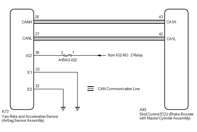
WIRING DIAGRAM
CAUTION / NOTICE / HINT
NOTICE:
-
After replacing or reinstalling the yaw rate and acceleration sensor (airbag sensor assembly), perform yaw rate and acceleration sensor zero point calibration after clearing previously calibrated data.
Click here
![2018 MY Camry HV [07/2017 - 09/2018]; BRAKE CONTROL / DYNAMIC CONTROL SYSTEMS: ELECTRONICALLY CONTROLLED BRAKE SYSTEM: CALIBRATION](/t3Portal/stylegraphics/info.gif)
- Inspect the fuses for circuits related to this system before performing the following procedure.
PROCEDURE
|
1. |
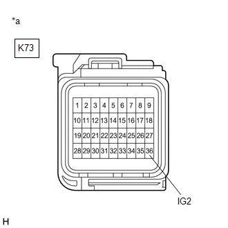
CHECK HARNESS AND CONNECTOR (IG2 TERMINAL) |
|
(a) Make sure that there is no looseness at the locking part and the connecting part of the connector. OK: The connector is securely connected. |
|
(b) Disconnect the K73 yaw rate and acceleration sensor (airbag sensor assembly) connector.
(c) Check both the connector case and the terminals for deformation and corrosion.
OK:
No deformation or corrosion.
(d) Turn the power switch on (IG).
(e) Measure the voltage according to the value(s) in the table below.
Standard Voltage:
|
Tester Connection |
Condition |
Specified Condition |
|---|---|---|
|
K73-36 (IG2) - Body ground |
Power switch on (IG) |
11 to 14 V |
| NG |

|
REPAIR OR REPLACE HARNESS OR CONNECTOR (IG2 CIRCUIT) |
|

|
2. |
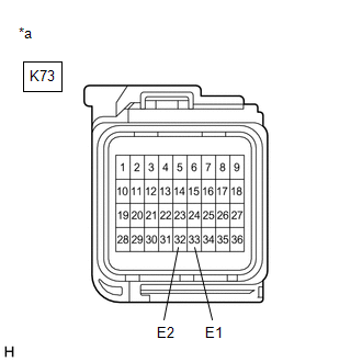
CHECK HARNESS AND CONNECTOR (GND TERMINAL) |
|
(a) Turn the power switch off. |
|
(b) Measure the resistance according to the value(s) in the table below.
Standard Resistance:
|
Tester Connection |
Condition |
Specified Condition |
|---|---|---|
|
K73-33 (E1) - Body ground |
Always |
Below 1 Ω |
|
K73-32 (E2) - Body ground |
Always |
Below 1 Ω |
| NG |
|
REPAIR OR REPLACE HARNESS OR CONNECTOR (GND CIRCUIT) |
|
|
3. |
RECONFIRM DTC |
(a) Reconnect the K73 yaw rate and acceleration sensor (airbag sensor assembly) connector.
(b) Clear the DTCs.
Chassis > ABS/VSC/TRAC > Clear DTCs
(c) Turn the power switch off.
(d) Turn the power switch on (READY).
(e) Perform a road test.
(f) Check if the same DTC is output.
Chassis > ABS/VSC/TRAC > Trouble Codes
|
Result |
Proceed to |
|---|---|
|
DTC C1381 is not output. |
A |
|
DTC C1381 is output. |
B |
| A |
|
| B |
|
|
|
|