| Last Modified: 02-14-2025 | 6.11:8.1.0 | Doc ID: RM1000000014VMW |
| Model Year Start: 2018 | Model: Camry HV | Prod Date Range: [07/2017 - 09/2018] |
| Title: BRAKE CONTROL / DYNAMIC CONTROL SYSTEMS: ELECTRONICALLY CONTROLLED BRAKE SYSTEM: C1352-C1359; Increasing Pressure Solenoid (FR); 2018 MY Camry HV [07/2017 - 09/2018] | ||
|
DTC |
C1352 |
Increasing Pressure Solenoid (FR) |
|
DTC |
C1353 |
Increasing Pressure Solenoid (FL) |
|
DTC |
C1354 |
Increasing Pressure Solenoid (RR) |
|
DTC |
C1355 |
Increasing Pressure Solenoid (RL) |
|
DTC |
C1356 |
Decreasing Pressure Solenoid (FR) |
|
DTC |
C1357 |
Decreasing Pressure Solenoid (FL) |
|
DTC |
C1358 |
Decreasing Pressure Solenoid (RR) |
|
DTC |
C1359 |
Decreasing Pressure Solenoid (RL) |
DESCRIPTION
Each solenoid adjusts the pressure which affects each wheel cylinder according to signals from the skid control ECU (brake booster with master cylinder assembly) and controls the vehicle.
|
DTC No. |
Detection Item |
INF Code |
DTC Detection Condition |
Trouble Area |
Note |
|---|---|---|---|---|---|
|
C1352 |
Increasing Pressure Solenoid (FR) |
11 1100 1101 1102 1103 1170 |
|
|
Electronically controlled brake system DTC |
|
C1353 |
Increasing Pressure Solenoid (FL) |
13 1106 1107 1108 1109 1172 |
|
|
Electronically controlled brake system DTC |
|
C1354 |
Increasing Pressure Solenoid (RR) |
15 1112 1113 1114 1115 1174 |
|
|
Electronically controlled brake system DTC |
|
C1355 |
Increasing Pressure Solenoid (RL) |
17 1118 1119 1120 1121 1176 |
|
|
Electronically controlled brake system DTC |
|
C1356 |
Decreasing Pressure Solenoid (FR) |
12 1104 1105 1171 |
|
|
Electronically controlled brake system DTC |
|
C1357 |
Decreasing Pressure Solenoid (FL) |
14 1110 1111 1173 |
|
|
Electronically controlled brake system DTC |
|
C1358 |
Decreasing Pressure Solenoid (RR) |
16 1116 1117 1175 |
|
|
Electronically controlled brake system DTC |
|
C1359 |
Decreasing Pressure Solenoid (RL) |
18 1122 1123 1177 |
|
|
Electronically controlled brake system DTC |
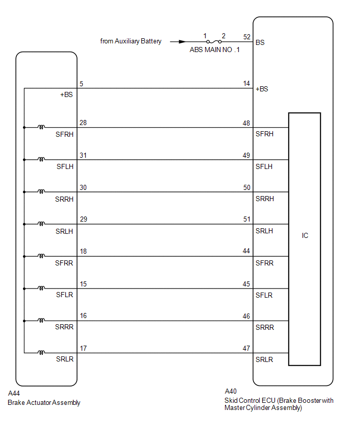
WIRING DIAGRAM
CAUTION / NOTICE / HINT
NOTICE:
After replacing the skid control ECU (brake booster with master cylinder assembly) or brake actuator assembly, perform linear solenoid valve offset learning, ABS holding solenoid valve learning, yaw rate and acceleration sensor zero point calibration and system information memorization after performing "Reset Memory".
Click here
![2018 MY Camry HV [07/2017 - 09/2018]; BRAKE CONTROL / DYNAMIC CONTROL SYSTEMS: ELECTRONICALLY CONTROLLED BRAKE SYSTEM: INITIALIZATION](/t3Portal/stylegraphics/info.gif)
PROCEDURE
|
1. |
INSPECT BRAKE ACTUATOR ASSEMBLY |
(a) Make sure that there is no looseness at the locking part and the connecting part of the connector.
OK:
The connector is securely connected.
|
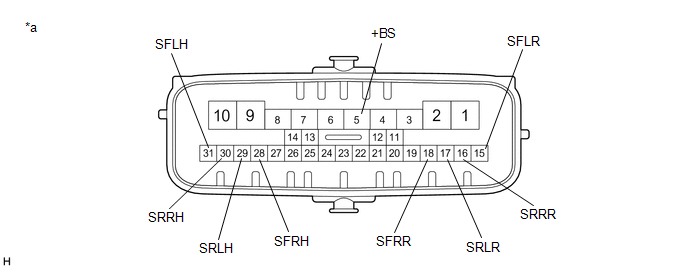
*a |
Component without harness connected (Brake Actuator Assembly) |
- |
- |
(b) Disconnect the A44 brake actuator assembly connector.
(c) Check both the connector case and the terminals for deformation and corrosion.
OK:
No deformation or corrosion.
(d) Measure the resistance according to the value(s) in the table below.
HINT:
Check the brake actuator assembly when it is cooled down.
Standard Resistance:
|
Tester Connection |
Condition |
Specified Condition |
|---|---|---|
|
5 (+BS) - 28 (SFRH) |
Always |
6.4 to 7.0 Ω |
|
5 (+BS) - 31 (SFLH) |
Always |
6.4 to 7.0 Ω |
|
5 (+BS) - 30 (SRRH) |
Always |
6.4 to 7.0 Ω |
|
5 (+BS) - 29 (SRLH) |
Always |
6.4 to 7.0 Ω |
|
5 (+BS) - 18 (SFRR) |
Always |
5.1 to 5.7 Ω |
|
5 (+BS) - 15 (SFLR) |
Always |
5.1 to 5.7 Ω |
|
5 (+BS) - 16 (SRRR) |
Always |
5.1 to 5.7 Ω |
|
5 (+BS) - 17 (SRLR) |
Always |
5.1 to 5.7 Ω |
| NG |

|
|

|
2. |
CHECK HARNESS AND CONNECTOR (BRAKE BOOSTER WITH MASTER CYLINDER ASSEMBLY - BRAKE ACTUATOR ASSEMBLY) |
(a) Make sure that there is no looseness at the locking part and the connecting part of the connector.
OK:
The connector is securely connected.
(b) Disconnect the A40 skid control ECU (brake booster with master cylinder assembly) connector.
(c) Check both the connector case and the terminals for deformation and corrosion.
OK:
No deformation or corrosion.
(d) Measure the resistance according to the value(s) in the table below.
Standard Resistance:
|
Tester Connection |
Condition |
Specified Condition |
|---|---|---|
|
A40-14 (+BS) - A44-5 (+BS) |
Always |
Below 1 Ω |
|
A40-14 (+BS) or A44-5 (+BS) - Body ground |
Always |
10 kΩ or higher |
|
A40-48 (SFRH) - A44-28 (SFRH) |
Always |
Below 1 Ω |
|
A40-48 (SFRH) or A44-28 (SFRH) - Body ground |
Always |
10 kΩ or higher |
|
A40-49 (SFLH) - A44-31 (SFLH) |
Always |
Below 1 Ω |
|
A40-49 (SFLH) or A44-31 (SFLH) - Body ground |
Always |
10 kΩ or higher |
|
A40-50 (SRRH) - A44-30 (SRRH) |
Always |
Below 1 Ω |
|
A40-50 (SRRH) or A44-30 (SRRH) - Body ground |
Always |
10 kΩ or higher |
|
A40-51 (SRLH) - A44-29 (SRLH) |
Always |
Below 1 Ω |
|
A40-51 (SRLH) or A44-29 (SRLH) - Body ground |
Always |
10 kΩ or higher |
|
A40-44 (SFRR) - A44-18 (SFRR) |
Always |
Below 1 Ω |
|
A40-44 (SFRR) or A44-18 (SFRR) - Body ground |
Always |
10 kΩ or higher |
|
A40-45 (SFLR) - A44-15 (SFLR) |
Always |
Below 1 Ω |
|
A40-45 (SFLR) or A44-15 (SFLR) - Body ground |
Always |
10 kΩ or higher |
|
A40-46 (SRRR) - A44-16 (SRRR) |
Always |
Below 1 Ω |
|
A40-46 (SRRR) or A44-16 (SRRR) - Body ground |
Always |
10 kΩ or higher |
|
A40-47 (SRLR) - A44-17 (SRLR) |
Always |
Below 1 Ω |
|
A40-47 (SRLR) or A44-17 (SRLR) - Body ground |
Always |
10 kΩ or higher |
| NG |
|
REPAIR OR REPLACE HARNESS OR CONNECTOR |
|
|
3. |
RECONFIRM DTC |
(a) Reconnect the A40 skid control ECU (brake booster with master cylinder assembly) connector.
(b) Reconnect the A44 brake actuator assembly connector.
(c) Clear the DTCs.
Chassis > ABS/VSC/TRAC > Clear DTCs
(d) Turn the power switch off.
(e) Turn the power switch on (IG).
(f) Check if the same DTC is output.
Chassis > ABS/VSC/TRAC > Trouble Codes
|
Result |
Proceed to |
|---|---|
|
DTCs C1352, C1353, C1354, C1355, C1356, C1357, C1358 and C1359 are not output. |
A |
|
DTCs C1352, C1353, C1354, C1355, C1356, C1357, C1358 and/or C1359 are output. |
B |
| A |
|
| B |
|
|
|
|