| Last Modified: 02-14-2025 | 6.11:8.1.0 | Doc ID: RM1000000014VM6 |
| Model Year Start: 2018 | Model: Camry HV | Prod Date Range: [07/2017 - 09/2018] |
| Title: BRAKE CONTROL / DYNAMIC CONTROL SYSTEMS: ELECTRONICALLY CONTROLLED BRAKE SYSTEM: C1300; Skid Control ECU Malfunction; 2018 MY Camry HV [07/2017 - 09/2018] | ||
|
DTC |
C1300 |
Skid Control ECU Malfunction |
DESCRIPTION
The skid control ECU (brake booster with master cylinder assembly) stores this DTC if malfunctions are found in the circuit inside the ECU by self diagnosis.
|
DTC No. |
Detection Item |
INF Code |
DTC Detection Condition |
Trouble Area |
Note |
|---|---|---|---|---|---|
|
C1300 |
Skid Control ECU Malfunction |
1028 to 1049 |
|
|
Electronically controlled brake system DTC |
WIRING DIAGRAM
Refer to DTCs C1252 and C1253.
Click here
![2018 MY Camry HV [07/2017 - 09/2018]; BRAKE CONTROL / DYNAMIC CONTROL SYSTEMS: ELECTRONICALLY CONTROLLED BRAKE SYSTEM: C1252,C1253; Brake Booster Pump Motor on Time Abnormally Long](/t3Portal/stylegraphics/info.gif)
CAUTION / NOTICE / HINT
NOTICE:
After replacing the skid control ECU (brake booster with master cylinder assembly), perform linear solenoid valve offset learning, ABS holding solenoid valve learning, yaw rate and acceleration sensor zero point calibration and system information memorization after performing "Reset Memory".
Click here
PROCEDURE
|
1. |
CHECK DTC |
(a) Clear the DTCs.
Chassis > ABS/VSC/TRAC > Clear DTCs
(b) Turn the power switch off.
(c) Turn the power switch on (IG).
(d) Check if the same DTC is output.
Chassis > ABS/VSC/TRAC > Trouble Codes
|
Result |
Proceed to |
|---|---|
|
A brake booster pump assembly circuit malfunction DTC is output with DTC C1300. |
A |
|
DTC C1300 is output. |
B |
| A |

|
|

|
2. |
CHECK FREEZE FRAME DATA |
(a) Check the INF code from the Freeze Frame Data stored when DTC (C1300) was stored.
Click here
Chassis > ABS/VSC/TRAC > Trouble Codes
|
Result |
Proceed to |
|---|---|
|
INF codes 1028 to 1044 or 1047 to 1049 are output. |
A |
|
INF code 1046 is output. |
B |
|
INF code 1045 is output. |
C |
| A |
|
| C |
|
|
|
3. |
CHECK FREEZE FRAME DATA |
(a) Using the Techstream, read the "IG1 Voltage Value", "IG2 Voltage Value", "BS1 Voltage Value", "BS2 Voltage Value", "VM1 Voltage Value" and "VM2 Voltage Value" of the Freeze Frame Data stored when the DTC C1300 (INF code 1046) was stored.
Click here
Chassis > ABS/VSC/TRAC > Trouble Codes
|
Result |
Proceed to |
|---|---|
|
Any of the voltage values of the Freeze Frame Data are 7.00 V or less. |
A |
|
All of the voltage values of the Freeze Frame Data are 12.00 V or more. |
B |
HINT:
If any of the voltage values of the Freeze Frame Data are 7.00 V or less, a sudden drop of the power source voltage is suspected as a cause of the DTC output.
In this case, inspect the auxiliary battery and replace or recharge the auxiliary battery as necessary.
| B |
|
|
|
4. |
CHECK AUXILIARY BATTERY |
(a) Check the auxiliary battery voltage.
Standard Voltage:
|
Tester Connection |
Condition |
Specified Condition |
|---|---|---|
|
Auxiliary battery |
Power switch on (IG) |
11 to 14 V |
|
Auxiliary battery |
Power switch on (READY) |
11 to 15.5 V |
| OK |
|
END |
| NG |
|
CHARGE OR REPLACE AUXILIARY BATTERY |
|
5. |
CHECK AUXILIARY BATTERY |
(a) Check the auxiliary battery voltage.
Standard Voltage:
|
Tester Connection |
Condition |
Specified Condition |
|---|---|---|
|
Auxiliary battery |
Power switch on (IG) |
11 to 14 V |
|
Auxiliary battery |
Power switch on (READY) |
11 to 15.5 V |
| OK |
|
| NG |
|
CHARGE OR REPLACE AUXILIARY BATTERY |
|
6. |
INSPECT BRAKE BOOSTER PUMP ASSEMBLY |
|
(a) Turn the power switch off. |
|
(b) Make sure that there is no looseness at the locking part and the connecting part of the connector.
OK:
The connector is securely connected.
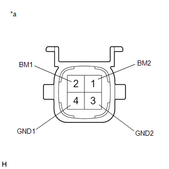
(c) Disconnect the A45 brake booster pump assembly connector.
(d) Check both the connector case and the terminals for deformation and corrosion.
OK:
No deformation or corrosion.
(e) Measure the resistance according to the value(s) in the table below.
Standard Resistance:
|
Tester Connection |
Condition |
Specified Condition |
|---|---|---|
|
2 (BM1) - 4 (GND1) |
Always |
10 Ω or less |
|
1 (BM2) - 3 (GND2) |
Always |
10 Ω or less |
|
2 (BM1) - 1 (BM2) |
Always |
Below 1 Ω |
|
4 (GND1) - 3 (GND2) |
Always |
Below 1 Ω |
| NG |
|
|
|
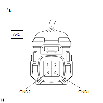
7. |
CHECK HARNESS AND CONNECTOR (GND TERMINAL) |
|
(a) Measure the resistance according to the value(s) in the table below. Standard Resistance:
|
|
| NG |
|
REPAIR OR REPLACE HARNESS OR CONNECTOR (GND CIRCUIT) |
|
|
8. |
CHECK HARNESS AND CONNECTOR (BRAKE BOOSTER WITH MASTER CYLINDER ASSEMBLY - BRAKE BOOSTER PUMP ASSEMBLY) |
(a) Make sure that there is no looseness at the locking part and the connecting part of the connector.
OK:
The connector is securely connected.
(b) Disconnect the A40 skid control ECU (brake booster with master cylinder assembly) connector.
(c) Check both the connector case and the terminals for deformation and corrosion.
OK:
No deformation or corrosion.
(d) Measure the resistance according to the value(s) in the table below.
Standard Resistance:
|
Tester Connection |
Condition |
Specified Condition |
|---|---|---|
|
A40-1 (MRO1) - A45-2 (BM1) |
Always |
Below 1 Ω |
|
A40-1 (MRO1) or A45-2 (BM1) - Body ground |
Always |
10 kΩ or higher |
|
A40-27 (MRO2) - A45-1 (BM2) |
Always |
Below 1 Ω |
|
A40-27 (MRO2) or A45-1 (BM2) - Body ground |
Always |
10 kΩ or higher |
| OK |
|
| NG |
|
REPAIR OR REPLACE HARNESS OR CONNECTOR |
|
|
|