| Last Modified: 02-14-2025 | 6.11:8.1.0 | Doc ID: RM1000000014VLS |
| Model Year Start: 2018 | Model: Camry HV | Prod Date Range: [07/2017 - 09/2018] |
| Title: BRAKE CONTROL / DYNAMIC CONTROL SYSTEMS: ELECTRONICALLY CONTROLLED BRAKE SYSTEM: C1241,C1242; Low or High Power Supply Voltage; 2018 MY Camry HV [07/2017 - 09/2018] | ||
|
DTC |
C1241 |
Low or High Power Supply Voltage |
|
DTC |
C1242 |
Open Circuit in IG1/IG2 Power Source Circuit |
DESCRIPTION
If a malfunction is detected in the power supply circuit, the skid control ECU (brake booster with master cylinder assembly) power source voltage drops, or there is insufficient voltage to operate the main relay, the skid control ECU (brake booster with master cylinder assembly) will store these DTCs.
If the auxiliary battery voltage is temporarily low, these DTCs may be stored.
HINT:
DTC C1256 (Accumulator Low Pressure) may also be memorized if there is a drop in power source voltage.
|
DTC No. |
Detection Item |
INF Code |
DTC Detection Condition |
Trouble Area |
Note |
|---|---|---|---|---|---|
|
C1241 |
Low or High Power Supply Voltage |
101 102 103 551 552 554 |
|
|
Electronically controlled brake system DTC |
|
C1242 |
Open Circuit in IG1/IG2 Power Source Circuit |
111 112 |
|
|
Electronically controlled brake system DTC |
DTC Detection Conditions: C1241 INF Code: 101
|
Vehicle Condition |
|||
|---|---|---|---|
|
Pattern 1 |
Pattern 2 |
||
|
Diagnosis Condition |
When the BS terminal voltage is 9.1 V or less. |
○ |
○ |
|
Malfunction Status |
The brake is not applied. |
○ |
- |
|
The brake is applied. |
- |
○ |
|
|
Detection Time |
3 seconds or more |
0.05 seconds or more |
|
|
Number of Trips |
1 trip |
1 trip |
|
HINT:
DTC will be output when conditions for either of the patterns in the table above are met.
DTC Detection Conditions: C1241 INF Code: 102
|
Vehicle Condition |
|||||||
|---|---|---|---|---|---|---|---|
|
Pattern 1 |
Pattern 2 |
Pattern 3 |
Pattern 4 |
Pattern 5 |
Pattern 6 |
||
|
Diagnosis Condition |
When the ECU internal voltage is 6.92 V or less. |
○ |
○ |
○ |
○ |
○ |
○ |
|
Malfunction Status |
The relay output voltage is less than 3.5 V, when the main relay operation command is on. |
○ |
- |
- |
- |
- |
- |
|
The value of the stroke sensor is invalid. |
- |
○ |
- |
- |
- |
- |
|
|
The value of the reaction force pressure sensor is invalid. |
- |
- |
○ |
- |
- |
- |
|
|
The servo pressure sensor power source voltage is 6.29 V or less, or 7.64 V or more. |
- |
- |
- |
○ |
- |
- |
|
|
The value of the servo pressure sensor is invalid. |
- |
- |
- |
- |
○ |
- |
|
|
The reaction force pressure sensor power source voltage is 6.29 V or less, or 7.64 V or more. |
- |
- |
- |
- |
- |
○ |
|
|
Detection Time |
0.05 seconds or more |
0.2 seconds or more |
0.2 seconds or more |
0.06 seconds or more |
0.2 seconds or more |
0.06 seconds or more |
|
|
Number of Trips |
1 trip |
1 trip |
1 trip |
1 trip |
1 trip |
1 trip |
|
HINT:
DTC will be output when conditions for either of the patterns in the table above are met.
DTC Detection Conditions: C1241 INF Code: 103
|
Vehicle Condition |
||||
|---|---|---|---|---|
|
Pattern 1 |
Pattern 2 |
Pattern 3 |
||
|
Diagnosis Condition |
ECU internal voltage is 8.3 V or less. |
○ |
- |
- |
|
ECU internal voltage is 6.9 V or less. |
- |
○ |
○ |
|
|
Malfunction Status |
The value of the accumulator pressure sensor is invalid. |
○ |
- |
- |
|
When the accumulator pressure sensor value is 15 MPa (153 kgf/cm2, 2176 psi) or less, the pump motor does not operate. |
- |
○ |
- |
|
|
Both the motor relay 1 and 2 cannot be operated. |
- |
- |
○ |
|
|
Detection Time |
0.8 seconds or more |
1 second or more |
0.2 seconds or more |
|
|
Number of Trips |
1 trip |
1 trip |
1 trip |
|
HINT:
DTC will be output when conditions for either of the patterns in the table above are met.
DTC Detection Conditions: C1241 INF Code: 551
|
Vehicle Condition |
|||
|---|---|---|---|
|
Pattern 1 |
Pattern 2 |
||
|
Diagnosis Condition |
The BS voltage of the ABS unit is 9.1 V or less. |
○ |
○ |
|
Malfunction Status |
The brake is not applied. |
○ |
- |
|
The brake is applied. |
- |
○ |
|
|
Detection Time |
3 seconds or more |
0.05 seconds or more |
|
|
Number of Trips |
1 trip |
1 trip |
|
HINT:
DTC will be output when conditions for either of the patterns in the table above are met.
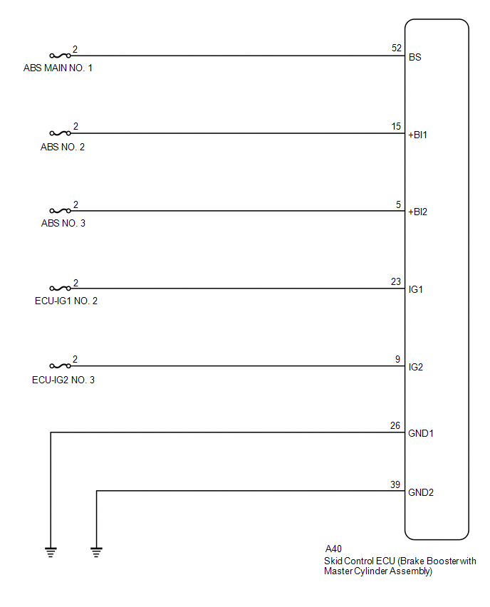
WIRING DIAGRAM
CAUTION / NOTICE / HINT
NOTICE:
-
After replacing the skid control ECU (brake booster with master cylinder assembly), perform linear solenoid valve offset learning, ABS holding solenoid valve learning, yaw rate and acceleration sensor zero point calibration and system information memorization after performing "Reset Memory".
Click here
![2018 MY Camry HV [07/2017 - 09/2018]; BRAKE CONTROL / DYNAMIC CONTROL SYSTEMS: ELECTRONICALLY CONTROLLED BRAKE SYSTEM: INITIALIZATION](/t3Portal/stylegraphics/info.gif)
- Inspect the fuses for circuits related to this system before performing the following procedure.
PROCEDURE
|
1. |
CHECK SMART KEY SYSTEM (for Start Function) |
(a) Check if smart key system (for start function) DTCs are output.
Body Electrical > Smart Key > Trouble Codes
Body Electrical > Power Source Control > Trouble Codes
|
Result |
Proceed to |
|---|---|
|
DTCs are not output. |
A |
|
DTCs are output. |
B |
| B |

|
|

|
2. |
CHECK DTC (HYBRID CONTROL SYSTEM) |
(a) Check if hybrid control system DTCs are output.
Powertrain > Hybrid Control > Trouble Codes
|
Result |
Proceed to |
|---|---|
|
DTCs are not output. |
A |
|
DTCs are output. |
B |
| B |
|
INSPECT HYBRID CONTROL SYSTEM for Nickel Metal Hydride Battery: Click here
for Lithium-ion Battery: Click here
|
|
|
3. |
CHECK DTC |
(a) Check that no main relay malfunction DTCs are output.
Chassis > ABS/VSC/TRAC > Trouble Codes
|
Result |
Proceed to |
|---|---|
|
Main relay malfunction DTCs are not output. |
A |
|
Main relay malfunction DTCs are output. |
B |
| B |
|
|
|
4. |
CHECK AUXILIARY BATTERY |
(a) Check the auxiliary battery voltage.
Standard Voltage:
|
Tester Connection |
Condition |
Specified Condition |
|---|---|---|
|
Auxiliary battery |
Power switch on (IG) |
11 to 14 V |
|
Auxiliary battery |
Power switch on (READY) |
11 to 15.5 V |
| NG |
|
CHARGE OR REPLACE AUXILIARY BATTERY |
|
|
5. |
CHECK HARNESS AND CONNECTOR (POWER SOURCE TERMINAL) |
|
(a) Turn the power switch off. |
|
(b) Make sure that there is no looseness at the locking part and the connecting part of the connector.
OK:
The connector is securely connected.
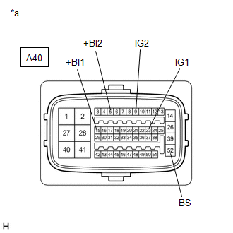
(c) Disconnect the A40 skid control ECU (brake booster with master cylinder assembly) connector.
(d) Check both the connector case and the terminals for deformation and corrosion.
OK:
No deformation or corrosion.
(e) Measure the voltage according to the value(s) in the table below.
Standard Voltage:
|
Tester Connection |
Condition |
Specified Condition |
|---|---|---|
|
A40-15 (+BI1) - Body ground |
Always |
11 to 14 V |
|
A40-5 (+BI2) - Body ground |
Always |
11 to 14 V |
|
A40-52 (BS) - Body ground |
Always |
11 to 14 V |
|
A40-23 (IG1) - Body ground |
Power switch on (IG) |
11 to 14 V |
|
A40-9 (IG2) - Body ground |
Power switch on (IG) |
11 to 14 V |
| NG |
|
REPAIR OR REPLACE HARNESS OR CONNECTOR (POWER SOURCE CIRCUIT) |
|
|
6. |
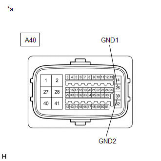
CHECK HARNESS AND CONNECTOR (GND TERMINAL) |
|
(a) Turn the power switch off. |
|
(b) Measure the resistance according to the value(s) in the table below.
Standard Resistance:
|
Tester Connection |
Condition |
Specified Condition |
|---|---|---|
|
A40-26 (GND1) - Body ground |
Always |
Below 1 Ω |
|
A40-39 (GND2) - Body ground |
Always |
Below 1 Ω |
| NG |
|
REPAIR OR REPLACE HARNESS OR CONNECTOR (GND CIRCUIT) |
|
|
7. |
RECONFIRM DTC |
(a) Reconnect the A40 skid control ECU (brake booster with master cylinder assembly) connector.
(b) Clear the DTCs.
Chassis > ABS/VSC/TRAC > Clear DTCs
(c) Turn the power switch off.
(d) Turn the power switch on (IG).
(e) Check if the same DTC is output.
Chassis > ABS/VSC/TRAC > Trouble Codes
|
Result |
Proceed to |
|---|---|
|
DTCs C1241 and C1242 are not output. |
A |
|
DTCs C1241 and/or C1242 are output. |
B |
| A |
|
| B |
|
|
|
|