| Last Modified: 02-14-2025 | 6.11:8.1.0 | Doc ID: RM1000000014VLR |
| Model Year Start: 2018 | Model: Camry HV | Prod Date Range: [07/2017 - 09/2018] |
| Title: BRAKE CONTROL / DYNAMIC CONTROL SYSTEMS: ELECTRONICALLY CONTROLLED BRAKE SYSTEM: C1311,C1312; Open Circuit in Main Relay 1; 2018 MY Camry HV [07/2017 - 09/2018] | ||
|
DTC |
C1311 |
Open Circuit in Main Relay 1 |
|
DTC |
C1312 |
Short Circuit in Main Relay 1 |
DESCRIPTION
The main relay supplies power to the switching solenoid and the linear solenoid.
The main relay remains on for approximately 2 minutes after the power switch is turned off and the input of brake pedal operation signals stops, and supplies power to the system to keep it ready to operate.
|
DTC No. |
Detection Item |
INF Code |
DTC Detection Condition |
Trouble Area |
Note |
|---|---|---|---|---|---|
|
C1311 |
Open Circuit in Main Relay 1 |
1 |
Either of the following is detected:
|
|
Electronically controlled brake system DTC |
|
C1312 |
Short Circuit in Main Relay 1 |
2 |
The BS terminal voltage is 3.5 V or more for 4.5 seconds or more, when operation of the main relay is requested. |
|
Electronically controlled brake system DTC |
DTC Detection Conditions: C1311 INF Code: 1
|
Vehicle Condition |
|||
|---|---|---|---|
|
Pattern 1 |
Pattern 2 |
||
|
Diagnosis Condition |
When the power switch is on (READY), the IG1 terminal voltage is 9.5 V or more. |
○ |
- |
|
When the power switch is off. |
- |
○ |
|
|
Malfunction Status |
The BS terminal voltage is less than 3.5 V, when operation of the main relay is requested. |
○ |
- |
|
The BS terminal voltage is less than 3.5 V, when operation of the main relay is requested. |
- |
○ |
|
|
Detection Time |
0.05 seconds or more |
0.05 seconds or more |
|
|
Number of Trips |
1 trip |
1 trip |
|
HINT:
DTC will be output when conditions for either of the patterns in the table above are met.
WIRING DIAGRAM
Refer to DTCs C1241 and C1242.
Click here
![2018 MY Camry HV [07/2017 - 09/2018]; BRAKE CONTROL / DYNAMIC CONTROL SYSTEMS: ELECTRONICALLY CONTROLLED BRAKE SYSTEM: C1241,C1242; Low or High Power Supply Voltage](/t3Portal/stylegraphics/info.gif)
CAUTION / NOTICE / HINT
NOTICE:
-
After replacing the brake booster with master cylinder assembly, perform linear solenoid valve offset learning, ABS holding solenoid valve learning, yaw rate and acceleration sensor zero point calibration and system information memorization after performing "Reset Memory".
Click here
- Inspect the fuses for circuits related to this system before performing the following procedure.
PROCEDURE
|
1. |
PERFORM ACTIVE TEST USING TECHSTREAM (MAIN RELAY) |
(a) Select the Active Test on the Techstream.
Chassis > ABS/VSC/TRAC > Active Test
|
Tester Display |
Measurement Item |
Control Range |
Diagnostic Note |
|---|---|---|---|
|
ECB Main Relay |
Main relay |
Relay ON/OFF |
ECB: Electronically Controlled Brake System |
Chassis > ABS/VSC/TRAC > Data List
|
Tester Display |
Measurement Item |
Range |
Normal Condition |
Diagnostic Note |
|---|---|---|---|---|
|
ECB Main Relay |
Main relay operation request |
ON or OFF |
ON: Relay on OFF: Relay off |
ECB: Electronically Controlled Brake System |
Chassis > ABS/VSC/TRAC > Active Test
|
Active Test Display |
|---|
|
ECB Main Relay |
|
Data List Display |
|---|
|
ECB Main Relay |
(b) Check that the condition of the main relay observed on the Techstream changes according to Techstream operation.
|
Result |
Proceed to |
|---|---|
|
Main relay in the Data List turns ON/OFF using the Active Test. |
A |
|
Main relay in the Data List does not change using the Active Test. |
B |
| B |

|
|

|
2. |
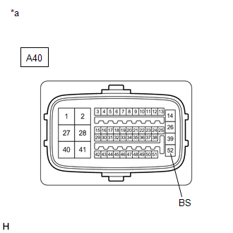
CHECK HARNESS AND CONNECTOR (BS TERMINAL) |
|
(a) Turn the power switch off. |
|
(b) Make sure that there is no looseness at the locking part and the connecting part of the connector.
OK:
The connector is securely connected.
(c) Disconnect the A40 skid control ECU (brake booster with master cylinder assembly) connector.
(d) Check both the connector case and the terminals for deformation and corrosion.
OK:
No deformation or corrosion.
(e) Measure the voltage according to the value(s) in the table below.
Standard Voltage:
|
Tester Connection |
Condition |
Specified Condition |
|---|---|---|
|
A40-52 (BS) - Body ground |
Always |
11 to 14 V |
| NG |
|
REPAIR OR REPLACE HARNESS OR CONNECTOR (BS CIRCUIT) |
|
|
3. |
RECONFIRM DTC |
(a) Reconnect the A40 skid control ECU (brake booster with master cylinder assembly) connector.
(b) Clear the DTCs.
Chassis > ABS/VSC/TRAC > Clear DTCs
(c) Turn the power switch off.
(d) Turn the power switch on (IG).
(e) Check if the same DTC is output.
Chassis > ABS/VSC/TRAC > Trouble Codes
|
Result |
Proceed to |
|---|---|
|
DTCs C1311 and C1312 are not output. |
A |
|
DTCs C1311 and/or C1312 are output. |
B |
| A |
|
| B |
|
|
4. |
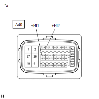
CHECK HARNESS AND CONNECTOR (+BI TERMINAL) |
|
(a) Turn the power switch off. |
|
(b) Make sure that there is no looseness at the locking part and the connecting part of the connector.
OK:
The connector is securely connected.
(c) Disconnect the A40 skid control ECU (brake booster with master cylinder assembly) connector.
(d) Check both the connector case and the terminals for deformation and corrosion.
OK:
No deformation or corrosion.
(e) Measure the voltage according to the value(s) in the table below.
Standard Voltage:
|
Tester Connection |
Condition |
Specified Condition |
|---|---|---|
|
A40-15 (+BI1) - Body ground |
Always |
11 to 14 V |
|
A40-5 (+BI2) - Body ground |
Always |
11 to 14 V |
| NG |
|
REPAIR OR REPLACE HARNESS OR CONNECTOR (+BI CIRCUIT) |
|
|
5. |
CHECK HARNESS AND CONNECTOR (BS TERMINAL) |
|
(a) Measure the voltage according to the value(s) in the table below. Standard Voltage:
|
|
| OK |
|
| NG |
|
REPAIR OR REPLACE HARNESS OR CONNECTOR (BS CIRCUIT) |
|
|
|