| Last Modified: 02-14-2025 | 6.11:8.1.0 | Doc ID: RM1000000014VLP |
| Model Year Start: 2018 | Model: Camry HV | Prod Date Range: [07/2017 - 09/2018] |
| Title: BRAKE CONTROL / DYNAMIC CONTROL SYSTEMS: ELECTRONICALLY CONTROLLED BRAKE SYSTEM: C1247,C1392; Stroke Sensor; 2018 MY Camry HV [07/2017 - 09/2018] | ||
|
DTC |
C1247 |
Stroke Sensor |
|
DTC |
C1392 |
Zero Point Calibration of Stroke Sensor undone |
DESCRIPTION
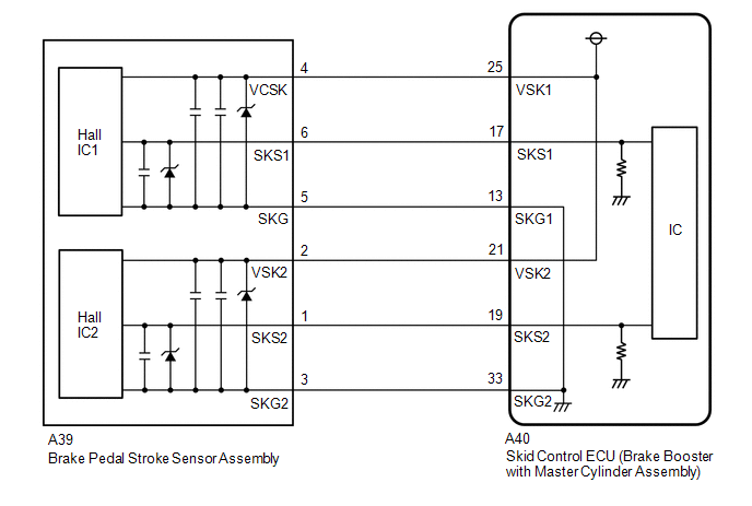
The brake pedal stroke sensor assembly sends a signal about the pedal stroke to the skid control ECU (brake booster with master cylinder assembly).
|
DTC No. |
Detection Item |
INF Code |
DTC Detection Condition |
Trouble Area |
Note |
|---|---|---|---|---|---|
|
C1247 |
Stroke Sensor |
211 212 213 214 215 216 217 |
|
|
Electronically controlled brake system DTC |
|
C1392 |
Zero Point Calibration of Stroke Sensor undone |
1124 |
The brake pedal stroke sensor assembly zero point calibration is not performed. (Normal brake pedal stroke sensor assembly zero point not memorized.) |
Normal brake pedal stroke sensor assembly zero point not memorized. (Linear solenoid valve offset learning is not performed or Test Mode is not performed or not complete.) |
Electronically controlled brake system DTC HINT: During Test Mode, related DTCs are cleared. |
WIRING DIAGRAM
CAUTION / NOTICE / HINT
NOTICE:
After replacing the skid control ECU (brake booster with master cylinder assembly) or brake pedal stroke sensor assembly, perform linear solenoid valve offset learning, ABS holding solenoid valve learning, yaw rate and acceleration sensor zero point calibration and system information memorization after performing "Reset Memory".
Click here
![2018 MY Camry HV [07/2017 - 09/2018]; BRAKE CONTROL / DYNAMIC CONTROL SYSTEMS: ELECTRONICALLY CONTROLLED BRAKE SYSTEM: INITIALIZATION](/t3Portal/stylegraphics/info.gif)
HINT:
Check the condition of each related circuit connector before troubleshooting.
Click here
PROCEDURE
|
1. |
CHECK BRAKE PEDAL |
(a) Check that the brake pedal and the brake pedal stroke sensor assembly are properly installed and that the pedal can be depressed normally.
(b) Check and adjust the brake pedal height.
Click here
(c) Adjust the brake pedal stroke sensor assembly.
Click here
|

|
2. |
CHECK HARNESS AND CONNECTOR (BRAKE BOOSTER WITH MASTER CYLINDER ASSEMBLY - BRAKE PEDAL STROKE SENSOR ASSEMBLY) |
(a) Make sure that there is no looseness at the locking part and the connecting part of the connectors.
OK:
The connector is securely connected.
(b) Disconnect the A40 skid control ECU (brake booster with master cylinder assembly) connector.
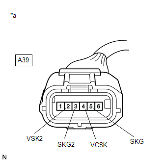
(c) Disconnect the A39 brake pedal stroke sensor assembly connector.
(d) Check both the connector case and the terminals for deformation and corrosion.
OK:
No deformation or corrosion.
(e) Measure the resistance according to the value(s) in the table below.
Standard Resistance:
|
Tester Connection |
Condition |
Specified Condition |
|---|---|---|
|
A40-13 (SKG1) - A39-5 (SKG) |
Always |
Below 1 Ω |
|
A40-13 (SKG1) or A39-5 (SKG) - Body ground |
Always |
10 kΩ or higher |
|
A40-17 (SKS1) - A39-6 (SKS1) |
Always |
Below 1 Ω |
|
A40-17 (SKS1) or A39-6 (SKS1) - Body ground |
Always |
10 kΩ or higher |
|
A40-19 (SKS2) - A39-1 (SKS2) |
Always |
Below 1 Ω |
|
A40-19 (SKS2) or A39-1 (SKS2) - Body ground |
Always |
10 kΩ or higher |
|
A40-21 (VSK2) - A39-2 (VSK2) |
Always |
Below 1 Ω |
|
A40-21 (VSK2) or A39-2 (VSK2) - Body ground |
Always |
10 kΩ or higher |
|
A40-25 (VSK1) - A39-4 (VCSK) |
Always |
Below 1 Ω |
|
A40-25 (VSK1) or A39-4 (VCSK) - Body ground |
Always |
10 kΩ or higher |
|
A40-33 (SKG2) - A39-3 (SKG2) |
Always |
Below 1 Ω |
|
A40-33 (SKG2) or A39-3 (SKG2) - Body ground |
Always |
10 kΩ or higher |
| NG |

|
REPAIR OR REPLACE HARNESS OR CONNECTOR |
|
|
3. |
INSPECT BRAKE BOOSTER WITH MASTER CYLINDER ASSEMBLY (SENSOR OUTPUT) |
|
(a) Reconnect the A40 skid control ECU (brake booster with master cylinder assembly) connector. |
|
(b) Turn the power switch on (IG).
(c) Measure the voltage according to the value(s) in the table below.
Standard Voltage:
|
Tester Connection |
Condition |
Specified Condition |
|---|---|---|
|
A39-4 (VCSK) - A39-5 (SKG) |
Power switch on (IG) |
4.84 to 5.16 V |
|
A39-2 (VSK2) - A39-3 (SKG2) |
Power switch on (IG) |
4.84 to 5.16 V |
| OK |
|
| NG |
|
|
|
|