| Last Modified: 02-14-2025 | 6.11:8.1.0 | Doc ID: RM1000000014VLM |
| Model Year Start: 2018 | Model: Camry HV | Prod Date Range: [07/2017 - 09/2018] |
| Title: BRAKE CONTROL / DYNAMIC CONTROL SYSTEMS: ELECTRONICALLY CONTROLLED BRAKE SYSTEM: C1252,C1253; Brake Booster Pump Motor on Time Abnormally Long; 2018 MY Camry HV [07/2017 - 09/2018] | ||
|
DTC |
C1252 |
Brake Booster Pump Motor on Time Abnormally Long |
|
DTC |
C1253 |
Pump Motor Relay |
DESCRIPTION
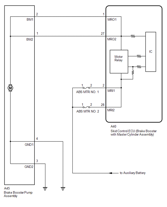
The skid control ECU (brake booster with master cylinder assembly) detects decreases in the accumulator pressure according to the data from the accumulator pressure sensor, and then starts and stops the pump motor by operating the motor relay.
|
DTC No. |
Detection Item |
INF Code |
DTC Detection Condition |
Trouble Area |
Note |
|---|---|---|---|---|---|
|
C1252 |
Brake Booster Pump Motor on Time Abnormally Long |
311 |
The pump motor is operating continuously for 178 seconds or more. (When the relay is malfunctioning for 98 seconds or more.) |
|
Electronically controlled brake system DTC |
|
C1253 |
Pump Motor Relay |
321 322 327 328 |
|
|
Electronically controlled brake system DTC |
WIRING DIAGRAM
CAUTION / NOTICE / HINT
NOTICE:
-
After replacing the skid control ECU (brake booster with master cylinder assembly), perform linear solenoid valve offset learning, ABS holding solenoid valve learning, yaw rate and acceleration sensor zero point calibration and system information memorization after performing "Reset Memory".
Click here
![2018 MY Camry HV [07/2017 - 09/2018]; BRAKE CONTROL / DYNAMIC CONTROL SYSTEMS: ELECTRONICALLY CONTROLLED BRAKE SYSTEM: INITIALIZATION](/t3Portal/stylegraphics/info.gif)
- Inspect the fuses for circuits related to this system before performing the following procedure.
PROCEDURE
|
1. |
READ VALUE USING TECHSTREAM (MOTOR RELAY 1 AND MOTOR RELAY 2) |
(a) Select the Data List on the Techstream.
Chassis > ABS/VSC/TRAC > Data List
|
Tester Display |
Measurement Item |
Range |
Normal Condition |
Diagnostic Note |
|---|---|---|---|---|
|
ECB Motor Relay |
Motor relay 1 operation request |
ON or OFF |
ON: Relay on OFF: Relay off |
ECB: Electronically Controlled Brake System |
|
ECB Motor Relay2 |
Motor relay 2 operation request |
ON or OFF |
ON: Relay on OFF: Relay off |
ECB: Electronically Controlled Brake System |
Chassis > ABS/VSC/TRAC > Data List
|
Tester Display |
|---|
|
ECB Motor Relay |
|
ECB Motor Relay2 |
(b) Depress the brake pedal several times and check the operation status of the motor relay 1 and motor relay 2.
HINT:
Depressing the brake pedal several times drops the accumulator pressure and operates the pump motor.
|
Result |
Proceed to |
|---|---|
|
The motor relay 1 and motor relay 2 in the Data List turns on or off by depressing the brake pedal several times. |
A |
|
The status of motor relay 1 and motor relay 2 in the Data List does not change even after depressing the brake pedal several times. |
B |
| B |

|
|

|
2. |
INSPECT BRAKE BOOSTER PUMP ASSEMBLY |
|
(a) Turn the power switch off. |
|
(b) Make sure that there is no looseness at the locking part and the connecting part of the connector.
OK:
The connector is securely connected.
(c) Disconnect the A45 brake booster pump assembly connector.
(d) Check both the connector case and the terminals for deformation and corrosion.
OK:
No deformation or corrosion.
(e) Measure the resistance according to the value(s) in the table below.
Standard Resistance:
|
Tester Connection |
Condition |
Specified Condition |
|---|---|---|
|
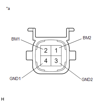
2 (BM1) - 4 (GND1) |
Always |
10 Ω or less |
|
1 (BM2) - 3 (GND2) |
Always |
10 Ω or less |
|
2 (BM1) - 1 (BM2) |
Always |
Below 1 Ω |
|
4 (GND1) - 3 (GND2) |
Always |
Below 1 Ω |
| NG |
|
|
|
3. |
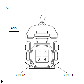
CHECK HARNESS AND CONNECTOR (GND TERMINAL) |
|
(a) Measure the resistance according to the value(s) in the table below. Standard Resistance:
|
|
| NG |
|
REPAIR OR REPLACE HARNESS OR CONNECTOR (GND CIRCUIT) |
|
|
4. |
READ VALUE USING TECHSTREAM (ACCUMULATOR PRESSURE) |
(a) Reconnect the A45 brake booster pump assembly connector.
(b) Disconnect the A39 brake pedal stroke sensor assembly connector.
(c) Select the Data List on the Techstream.
Chassis > ABS/VSC/TRAC > Data List
|
Tester Display |
Measurement Item |
Range |
Normal Condition |
Diagnostic Note |
|---|---|---|---|---|
|
MT Voltage Value |
MT voltage value |
Min.: 0.00 V, Max.: 20.00 V |
Pump motor off: 0.00 V Pump motor on: 12.00 V |
- |
|
Accumulator Pressure |
Accumulator pressure output value |
Min.: 0.00 MPa, Max.: 24.48 MPa |
15.00 to 21.00 MPa (Pressure stable and pump motor stopped) |
When brake fluid is stored in the accumulator: Accumulator pressure changes in accordance with volume of fluid stored in the accumulator |
Chassis > ABS/VSC/TRAC > Data List
|
Tester Display |
|---|
|
MT Voltage Value |
|
Accumulator Pressure |
(d) Depress the brake pedal several times to operate the pump motor, then wait until it stops.
(e) After the pump motor stops, wait for 30 seconds, then check the drop in the accumulator pressure sensor output value and the state of the pump motor.
HINT:
- This inspection checks whether an accumulator pressure sensor malfunction, internal brake actuator (brake booster with master cylinder assembly) leak or prolonged operation due to detection of low pressure caused by accumulator deterioration, caused the DTC to be stored.
- If the brake fluid level in the brake master cylinder reservoir assembly (brake booster with master cylinder assembly) drops, an external brake fluid leak is suspected.
|
Result |
Proceed to |
|---|---|
|
The drop in the accumulator pressure sensor output value is less than 2.50 MPa 30 seconds after the pump motor stops, and the pump motor does not operate within 30 seconds after the pump motor stops. |
A |
|
The drop in the accumulator pressure sensor output value is 2.50 MPa or more 30 seconds after the pump motor stops, or the pump motor operates within 30 seconds after the pump motor stops. |
B |
| B |
|
|
|
5. |
RECONFIRM DTC |
(a) Turn the power switch off.
(b) Reconnect the A39 brake pedal stroke sensor assembly connector.
(c) Clear the DTCs.
Chassis > ABS/VSC/TRAC > Clear DTCs
(d) Turn the power switch off.
(e) Turn the power switch on (IG).
(f) Check if the same DTC is output.
Chassis > ABS/VSC/TRAC > Trouble Codes
|
Result |
Proceed to |
|---|---|
|
DTCs C1252 and C1253 are not output. |
A |
|
DTCs C1252 and/or C1253 are output. |
B |
| A |
|
| B |
|
|
6. |
READ VALUE USING TECHSTREAM (SERVO PRESSURE) |
(a) Turn the power switch off.
(b) Reconnect the A39 brake pedal stroke sensor assembly connector.
(c) Select the Active Test on the Techstream.
Chassis > ABS/VSC/TRAC > Active Test
|
Tester Display |
Measurement Item |
Control Range |
Diagnostic Note |
|---|---|---|---|
|
ECB Solenoid (SLR) |
Linear solenoid reduction valve (SLR) |
Solenoid ON/OFF |
ECB: Electronically Controlled Brake System |
Chassis > ABS/VSC/TRAC > Data List
|
Tester Display |
Measurement Item |
Range |
Normal Condition |
Diagnostic Note |
|---|---|---|---|---|
|
Servo Pressure |
Pressure value of servo |
Min.: 0.00 MPa, Max.: 24.48 MPa |
Brake pedal released: 0.00 to 2.10 MPa |
Brake pedal is being depressed: Changes in proportion to the depression force of the brake pedal |
Chassis > ABS/VSC/TRAC > Active Test
|
Active Test Display |
|---|
|
ECB Solenoid (SLR) |
|
Data List Display |
|---|
|
Servo Pressure |
(d) Perform the Active Test and operate the linear solenoid (SLR) in the brake actuator (brake booster with master cylinder assembly).
(e) Check that the servo pressure output value does not increase when performing the Active Test.
OK:
The servo pressure output value does not increase when performing the Active Test.
HINT:
If the servo pressure output value increases, an internal brake fluid leak in the brake actuator (brake booster with master cylinder assembly) is suspected.
|
Result |
Proceed to |
|---|---|
|
The servo pressure output value increases. |
A |
|
The servo pressure output value does not increase. |
B |
| A |
|
| B |
|
|
7. |
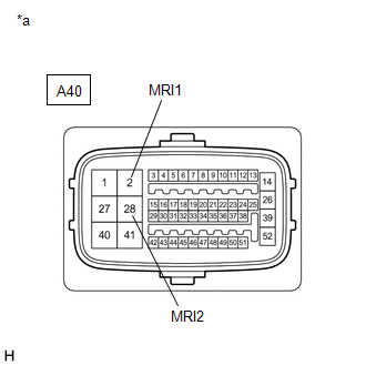
CHECK HARNESS AND CONNECTOR (MRI TERMINAL) |
|
(a) Turn the power switch off. |
|
(b) Make sure that there is no looseness at the locking part and the connecting part of the connector.
OK:
The connector is securely connected.
(c) Disconnect the A40 skid control ECU (brake booster with master cylinder assembly) connector.
(d) Check both the connector case and the terminals for deformation and corrosion.
OK:
No deformation or corrosion.
(e) Measure the voltage according to the value(s) in the table below.
Standard Voltage:
|
Tester Connection |
Condition |
Specified Condition |
|---|---|---|
|
A40-2 (MRI1) - Body ground |
Always |
11 to 14 V |
|
A40-28 (MRI2) - Body ground |
Always |
11 to 14 V |
| NG |
|
REPAIR OR REPLACE HARNESS OR CONNECTOR (MRI CIRCUIT) |
|
|
8. |
CHECK HARNESS AND CONNECTOR (BRAKE BOOSTER WITH MASTER CYLINDER ASSEMBLY - BRAKE BOOSTER PUMP ASSEMBLY) |
(a) Make sure that there is no looseness at the locking part and the connecting part of the connector.
OK:
The connector is securely connected.
(b) Disconnect the A45 brake booster pump assembly connector.
(c) Check both the connector case and the terminals for deformation and corrosion.
OK:
No deformation or corrosion.
(d) Measure the resistance according to the value(s) in the table below.
Standard Resistance:
|
Tester Connection |
Condition |
Specified Condition |
|---|---|---|
|
A40-1 (MRO1) - A45-2 (BM1) |
Always |
Below 1 Ω |
|
A40-1 (MRO1) or A45-2 (BM1) - Body ground |
Always |
10 kΩ or higher |
|
A40-27 (MRO2) - A45-1 (BM2) |
Always |
Below 1 Ω |
|
A40-27 (MRO2) or A45-1 (BM2) - Body ground |
Always |
10 kΩ or higher |
| OK |
|
| NG |
|
REPAIR OR REPLACE HARNESS OR CONNECTOR |
|
|
|