| Last Modified: 02-14-2025 | 6.11:8.1.0 | Doc ID: RM1000000014UGL |
| Model Year Start: 2018 | Model: Camry HV | Prod Date Range: [07/2017 - ] |
| Title: HYBRID / BATTERY CONTROL: HYBRID CONTROL SYSTEM (for NICKEL METAL HYDRIDE BATTERY): ECU Power Source Circuit; 2018 - 2024 MY Camry HV [07/2017 - ] | ||
|
ECU Power Source Circuit |
DESCRIPTION
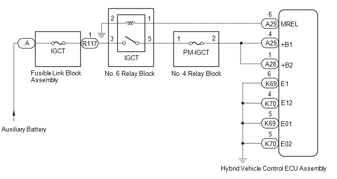
If the power switch is on (IG), the hybrid vehicle control ECU assembly applies current to the MREL terminal to turn the IGCT relay on. This supplies power to the +B1 and +B2 terminals.
WIRING DIAGRAM
CAUTION / NOTICE / HINT
NOTICE:
After turning the power switch off, waiting time may be required before disconnecting the cable from the negative (-) auxiliary battery terminal. Therefore, make sure to read the disconnecting the cable from the negative (-) auxiliary battery terminal notices before proceeding with work.
Click here
![2018 - 2019 MY Camry HV [07/2017 - 09/2019]; INTRODUCTION: REPAIR INSTRUCTION: PRECAUTION](/t3Portal/stylegraphics/info.gif)
PROCEDURE
|
1. |
CHECK HYBRID VEHICLE CONTROL ECU ASSEMBLY (+B1, +B2 VOLTAGE) |
(a) Turn the power switch on (IG).
|
(b) Measure the voltage according to the value(s) in the table below. Standard Voltage:
|
|
(c) Turn the power switch off.
| NG |

|
|

|
2. |
CHECK HARNESS AND CONNECTOR (HYBRID VEHICLE CONTROL ECU ASSEMBLY - BODY GROUND) |
(a) Disconnect the K69 and K70 hybrid vehicle control ECU assembly connectors.
|
(b) Measure the resistance according to the value(s) in the table below. Standard Resistance:
|
|
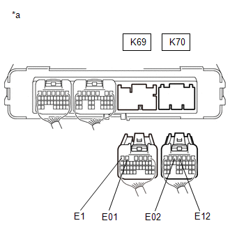
(c) Reconnect the K69 and K70 hybrid vehicle control ECU assembly connectors.
| OK |
|
GO TO PROBLEM SYMPTOMS TABLE
|
| NG |
|
REPAIR OR REPLACE HARNESS OR CONNECTOR |
|
3. |
CHECK HYBRID VEHICLE CONTROL ECU ASSEMBLY (MREL VOLTAGE) |
(a) Turn the power switch on (IG).
|
(b) Measure the voltage according to the value(s) in the table below. Standard Voltage:
|
|
(c) Turn the power switch off.
| NG |
|
REPLACE HYBRID VEHICLE CONTROL ECU ASSEMBLY
|
|
|
4. |
CHECK FUSE (PM-IGCT) |
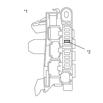
|
(a) Remove the PM-IGCT fuse from the No. 4 relay block. |
|
(b) Measure the resistance according to the value(s) in the table below.
Standard Resistance:
|
Tester Connection |
Condition |
Specified Condition |
|---|---|---|
|
PM-IGCT fuse terminals |
Always |
Below 1 Ω |
(c) Install the PM-IGCT fuse.
| NG |
|
|
|
5. |
CHECK FUSIBLE LINK BLOCK ASSEMBLY (IGCT FUSE) |
(a) Disconnect the cable from the negative (-) auxiliary battery terminal.
(b) Disconnect the cable from the positive (+) auxiliary battery terminal.
|
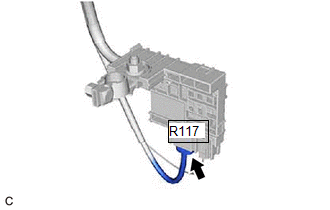
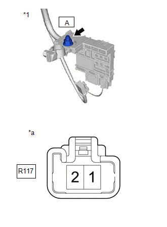
(c) Disconnect the R117 fusible link block assembly connector. |
|
|
(d) Measure the resistance according to the value(s) in the table below. Standard Resistance:
|
|
(e) Reconnect the R117 fusible link block assembly connector.
(f) Reconnect the cable to the positive (+) auxiliary battery terminal.
(g) Reconnect the cable to the negative (-) auxiliary battery terminal.
| NG |
|
|
|
6. |
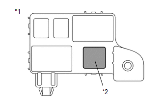
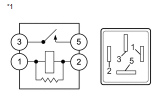
INSPECT RELAY (IGCT) |
|
(a) Remove the IGCT relay from the No. 6 relay block. |
|
|
(b) Measure the resistance according to the value(s) in the table below. Standard Resistance:
|
|
(c) Install the IGCT relay.
| NG |
|
REPLACE RELAY (IGCT) |
|
|
7. |
CHECK HARNESS AND CONNECTOR (NO. 4 RELAY BLOCK - HYBRID VEHICLE CONTROL ECU ASSEMBLY) |
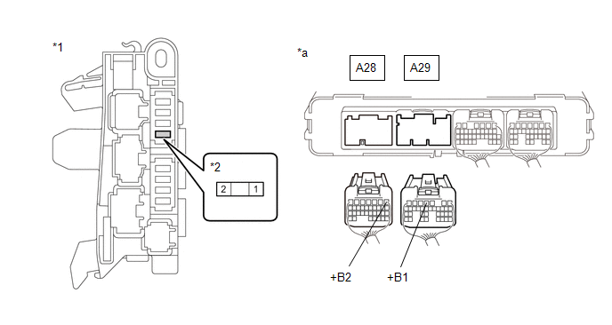
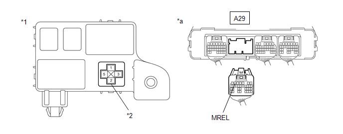
(a) Disconnect the A28 and A29 hybrid vehicle control ECU assembly connectors.
(b) Remove the PM-IGCT fuse from the No. 4 relay block.
(c) Measure the resistance according to the value(s) in the table below.
|
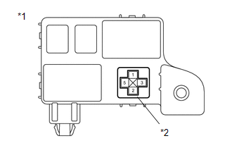
*1 |
No. 4 Relay Block |
*2 |
PM-IGCT Fuse |
|
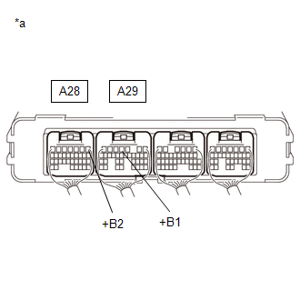
*a |
Rear view of wire harness connector (to Hybrid Vehicle Control ECU Assembly) |
- |
- |
Standard Resistance:
|
Tester Connection |
Condition |
Specified Condition |
|---|---|---|
|
A29-4 (+B1) - 2 (PM-IGCT fuse) |
Always |
Below 1 Ω |
|
A28-1 (+B2) - 2 (PM-IGCT fuse) |
Always |
Below 1 Ω |
(d) Reconnect the A28 and A29 hybrid vehicle control ECU assembly connectors.
(e) Install the PM-IGCT fuse.
| NG |
|
REPAIR OR REPLACE HARNESS OR CONNECTOR |
|
|
8. |
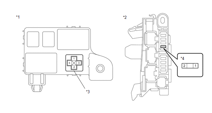
CHECK HARNESS AND CONNECTOR (NO. 6 RELAY BLOCK - NO. 4 RELAY BLOCK) |
(a) Remove the IGCT relay from the No. 6 relay block.
(b) Remove the PM-IGCT fuse from the No. 4 relay block.
(c) Measure the resistance according to the value(s) in the table below.
|
*1 |
No. 6 Relay Block |
*2 |
No. 4 Relay Block |
|
*3 |
IGCT Relay |
*4 |
PM-IGCT Fuse |
Standard Resistance:
|
Tester Connection |
Condition |
Specified Condition |
|---|---|---|
|
5 (IGCT relay) - 1 (PM-IGCT fuse) |
Always |
Below 1 Ω |
(d) Install the PM-IGCT fuse.
(e) Install the IGCT relay.
| NG |
|
REPAIR OR REPLACE HARNESS OR CONNECTOR |
|
|
9. |
CHECK HARNESS AND CONNECTOR (FUSIBLE LINK BLOCK ASSEMBLY - NO. 6 RELAY BLOCK) |
(a) Disconnect the R117 fusible link block assembly connector.
|
(b) Remove the IGCT relay from the No. 6 relay block. |
|
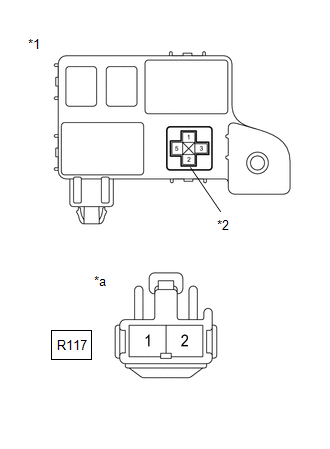
(c) Measure the resistance according to the value(s) in the table below.
Standard Resistance:
|
Tester Connection |
Condition |
Specified Condition |
|---|---|---|
|
3 (IGCT relay) - R117-1 |
Always |
Below 1 Ω |
(d) Install the IGCT relay.
(e) Reconnect the R117 fusible link block assembly connector.
| NG |
|
REPAIR OR REPLACE HARNESS OR CONNECTOR |
|
|
10. |
CHECK HARNESS AND CONNECTOR (HYBRID VEHICLE CONTROL ECU ASSEMBLY - NO. 6 RELAY BLOCK) |
(a) Disconnect the A29 hybrid vehicle control ECU assembly connector.
(b) Remove the IGCT relay from the No. 6 relay block.
(c) Measure the resistance according to the value(s) in the table below.
|
*1 |
No. 6 Relay Block |
*2 |
IGCT Relay |
|
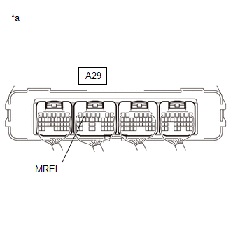
*a |
Rear view of wire harness connector (to Hybrid Vehicle Control ECU Assembly) |
- |
- |
Standard Resistance:
|
Tester Connection |
Condition |
Specified Condition |
|---|---|---|
|
A29-6 (MREL) - 1 (IGCT relay) |
Always |
Below 1 Ω |
|
A29-6 (MREL) or 1 (IGCT relay) - Body ground and other terminals |
Always |
10 kΩ or higher |
(d) Install the IGCT relay.
(e) Reconnect the A29 hybrid vehicle control ECU assembly connector.
| NG |
|
REPAIR OR REPLACE HARNESS OR CONNECTOR |
|
|
11. |
CHECK HARNESS AND CONNECTOR (NO. 6 RELAY BLOCK - BODY GROUND) |
(a) Remove the IGCT relay from the No. 6 relay block.
|
(b) Measure the resistance according to the value(s) in the table below. Standard Resistance:
|
|
(c) Install the IGCT relay.
| OK |
|
| NG |
|
REPAIR OR REPLACE HARNESS OR CONNECTOR |
|
12. |
CHECK HARNESS AND CONNECTOR (NO. 4 RELAY BLOCK - HYBRID VEHICLE CONTROL ECU ASSEMBLY) |
(a) Remove the PM-IGCT fuse from the No. 4 relay block.
(b) Disconnect the A28 and A29 hybrid vehicle control ECU assembly connectors.
(c) Measure the resistance according to the value(s) in the table below.
|
*1 |
No. 4 Relay Block |
*2 |
PM-IGCT Fuse |
|
*a |
Rear view of wire harness connector (to Hybrid Vehicle Control ECU Assembly) |
- |
- |
Standard Resistance:
|
Tester Connection |
Condition |
Specified Condition |
|---|---|---|
|
A29-4 (+B1) or 2 (PM-IGCT fuse) - Body ground and other terminals |
Always |
10 kΩ or higher |
|
A28-1 (+B2) or 2 (PM-IGCT fuse) - Body ground and other terminals |
Always |
10 kΩ or higher |
(d) Reconnect the A28 and A29 hybrid vehicle control ECU assembly connectors.
(e) Install the PM-IGCT fuse.
| OK |
|
REPLACE FUSE (PM-IGCT) |
| NG |
|
|
13. |
CHECK HARNESS AND CONNECTOR (FUSIBLE LINK BLOCK ASSEMBLY - NO. 6 RELAY BLOCK) |
(a) Disconnect the R117 fusible link block assembly connector.
(b) Remove the IGCT relay from the No. 6 relay block.
|
(c) Measure the resistance according to the value(s) in the table below. Standard Resistance:
|
|
(d) Install the IGCT relay.
(e) Reconnect the R117 fusible link block assembly connector.
| NG |
|
|
|
14. |
CHECK HARNESS AND CONNECTOR (NO. 6 RELAY BLOCK - NO. 4 RELAY BLOCK) |
(a) Remove the IGCT relay from the No. 6 relay block.
(b) Remove the PM-IGCT fuse from the No. 4 relay block.
(c) Measure the resistance according to the value(s) in the table below.
|
*1 |
No. 6 Relay Block |
*2 |
No. 4 Relay Block |
|
*3 |
IGCT Relay |
*4 |
PM-IGCT Fuse |
Standard Resistance:
|
Tester Connection |
Condition |
Specified Condition |
|---|---|---|
|
5 (IGCT relay) or 1 (PM-IGCT fuse) - Body ground and other terminals |
Always |
10 kΩ or higher |
(d) Install the PM-IGCT fuse.
(e) Install the IGCT relay.
| OK |
|
REPLACE FUSIBLE LINK BLOCK ASSEMBLY (IGCT FUSE) |
| NG |
|
|
15. |
REPAIR OR REPLACE HARNESS OR CONNECTOR |
| NEXT |
|
REPLACE FUSE (PM-IGCT) |
|
16. |
REPAIR OR REPLACE HARNESS OR CONNECTOR |
| NEXT |
|
REPLACE FUSIBLE LINK BLOCK ASSEMBLY (IGCT FUSE) |
|
17. |
REPAIR OR REPLACE HARNESS OR CONNECTOR |
| NEXT |
|
REPLACE FUSIBLE LINK BLOCK ASSEMBLY (IGCT FUSE) |
|
|
|