| Last Modified: 02-14-2025 | 6.11:8.1.0 | Doc ID: RM1000000014U4A |
| Model Year Start: 2018 | Model: Camry HV | Prod Date Range: [07/2017 - 09/2018] |
| Title: NETWORKING: CAN COMMUNICATION SYSTEM: TERMINALS OF ECU; 2018 MY Camry HV [07/2017 - 09/2018] | ||
TERMINALS OF ECU
NOTICE:
-
After turning the power switch off, waiting time may be required before disconnecting the cable from the negative (-) auxiliary battery terminal. Therefore, make sure to read the disconnecting the cable from the negative (-) auxiliary battery terminal notices before proceeding with work.
Click here
![2018 - 2019 MY Camry HV [07/2017 - 09/2019]; INTRODUCTION: REPAIR INSTRUCTION: PRECAUTION](/t3Portal/stylegraphics/info.gif)
- Before measuring the resistance of the CAN bus, turn the power switch off and leave the vehicle for 1 minute or more without operating the key or any switches, or opening or closing the doors. After that, disconnect the cable from the negative (-) auxiliary battery terminal and leave the vehicle for 1 minute or more before measuring the resistance.
- This section describes the standard values for all CAN related components.
HINT:
-
The systems (ECUs and sensors) that use CAN communication vary depending on the vehicle and optional equipment. Check which systems (ECUs and sensors) are installed to the vehicle.
Click here
- Operating the power switch, any other switches or a door triggers related ECU and sensor communication on the CAN. This communication will cause the resistance value to change.
- Even after DTCs are cleared, if a DTC is stored again after driving the vehicle for a while, the malfunction may be occurring due to vibration of the vehicle. In such a case, wiggling the ECUs or wire harness while performing the inspection below may help determine the cause of the malfunction.
NO. 1 CAN JUNCTION CONNECTOR
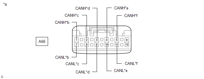
(a) Check the No. 1 CAN junction connector.
(1) Connection diagram
|
*a |
Front view of wire harness connector (to No. 1 CAN Junction Connector) |
*b |
to Millimeter Wave Radar Sensor Assembly |
|
*c |
to Forward Recognition Camera |
*d |
to Central Gateway ECU (Network Gateway ECU) |
|
*e |
to Swing Grille Actuator Assembly |
*f |
to No. 5 CAN Junction Connector |
(2) Check the connection diagram of the components which are connected to the No. 1 CAN junction connector.
|
Terminal No. (Symbol) |
Wiring Color |
Connected to |
|---|---|---|
|
A66-1 (CANH) |
R |
Millimeter wave radar sensor assembly (for Bus 1) |
|
A66-7 (CANL) |
W |
|
|
A66-2 (CANH) |
G |
Forward recognition camera (for Bus 1) |
|
A66-8 (CANL) |
W |
|
|
A66-3 (CANH) |
P |
Central gateway ECU (network gateway ECU) (for Bus 1) |
|
A66-9 (CANL) |
W |
|
|
A66-4 (CANH) |
G |
Swing grille actuator assembly (for Bus 1) |
|
A66-10 (CANL) |
W |
|
|
A66-5 (CANH) |
B |
No. 5 CAN junction connector (for Bus 1) |
|
A66-11 (CANL) |
W |
NO. 2 CAN JUNCTION CONNECTOR
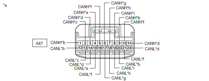
(a) Check the No. 2 CAN junction connector.
(1) Connection diagram
|
*a |
Front view of wire harness connector (to No. 2 CAN Junction Connector) |
*b |
to Brake Booster with Master Cylinder Assembly |
|
*c |
to No. 3 Junction Connector |
*d |
to ECM |
|
*e |
to Rack and Pinion Power Steering Gear Assembly |
*f |
to No. 4 CAN Junction Connector |
|
*g |
to Brake Actuator Assembly |
*h |
to Battery ECU Assembly (for Lithium-ion Battery) |
|
*i |
to Inverter with Converter Assembly |
- |
- |
(2) Check the connection diagram of the components which are connected to the No. 2 CAN junction connector.
|
Terminal No. (Symbol) |
Wiring Color |
Connected to |
|---|---|---|
|
A67-1 (CANH) |
Y |
brake booster with master cylinder assembly (for Bus 4) |
|
A67-12 (CANL) |
W |
|
|
A67-2 (CANH) |
R |
No. 3 junction connector (for Bus 4) |
|
A67-13 (CANL) |
W |
|
|
A67-3 (CANH) |
P |
ECM (for Bus 4) |
|
A67-14 (CANL) |
W |
|
|
A67-4 (CANH) |
G |
Rack and pinion power steering gear assembly (for Bus 4) |
|
A67-15 (CANL) |
W |
|
|
A67-5 (CANH) |
GR |
No. 4 CAN junction connector (for Bus 4) |
|
A67-16 (CANL) |
W |
|
|
A67-6 (CANH) |
B |
Brake actuator assembly (for Bus 4) |
|
A67-17 (CANL) |
W |
|
|
A67-7 (CANH) |
Y |
Battery ECU assembly* (for Bus 2) |
|
A67-18 (CANL) |
W |
|
|
A67-8 (CANH) |
V |
Inverter with Converter Assembly (for Bus 2) |
|
A67-19 (CANL) |
W |
|
|
A67-9 (CANH) |
LG |
Brake booster with master cylinder assembly (for Bus 2) |
|
A67-20 (CANL) |
W |
|
|
A67-10 (CANH) |
L |
No. 4 CAN junction connector (for Bus 2) |
|
A67-21 (CANL) |
W |
|
|
A67-11 (CANH) |
B |
ECM (for Bus 2) |
|
A67-22 (CANL) |
W |
- *: for Lithium-ion Battery
NO. 3 CAN JUNCTION CONNECTOR
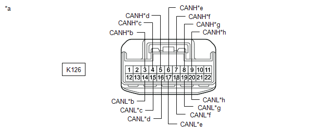
(a) Check the No. 3 CAN junction connector.
(1) Connection diagram
|
*a |
Front view of wire harness connector (to No. 3 CAN Junction Connector) |
*b |
to No. 1 Junction Connector |
|
*c |
to Certification ECU (Smart Key ECU Assembly) |
*d |
to Combination Meter Assembly |
|
*e |
to Main Body ECU (Multiplex Network Body ECU) |
*f |
to Air Conditioning Amplifier Assembly |
|
*g |
to Headlight ECU Sub-assembly LH (w/ AFS) |
*h |
to Meter Mirror Sub-assembly (w/ Headup Display System) |
(2) Check the connection diagram of the components which are connected to the No. 3 CAN junction connector.
|
Terminal No. (Symbol) |
Wiring Color |
Connected to |
|---|---|---|
|
K126-3 (CANH) |
P |
No. 1 junction connector (for Bus 5) |
|
K126-14 (CANL) |
W |
|
|
K126-4 (CANH) |
G |
Certification ECU (smart key ECU assembly) (for Bus 5) |
|
K126-15 (CANL) |
W |
|
|
K126-5 (CANH) |
B |
Combination meter assembly (for Bus 5) |
|
K126-16 (CANL) |
W |
|
|
K126-6 (CANH) |
BE |
Main body ECU (multiplex network body ECU) (for Bus 5) |
|
K126-17 (CANL) |
W |
|
|
K126-7 (CANH) |
SB |
Air conditioning amplifier assembly (for Bus 5) |
|
K126-18 (CANL) |
W |
|
|
K126-8 (CANH) |
L |
Headlight ECU sub-assembly LH*1 (for Bus 5) |
|
K126-19 (CANL) |
W |
|
|
K126-9 (CANH) |
LG |
Meter mirror sub-assembly*2 (for Bus 5) |
|
K126-20 (CANL) |
W |
- *1: w/ AFS
- *2: w/ Headup Display System
NO. 4 CAN JUNCTION CONNECTOR
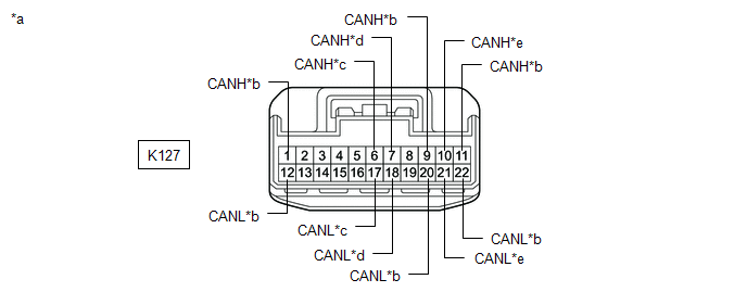
(a) Check the No. 4 CAN junction connector.
(1) Connection diagram
|
*a |
Front view of wire harness connector (to No. 4 CAN Junction Connector) |
*b |
to Central Gateway ECU (Network Gateway ECU) |
|
*c |
to No. 2 CAN Junction Connector |
*d |
to Steering Sensor |
|
*e |
to DCM (Telematics Transceiver) (w/ Telematics Transceiver) |
- |
- |
(2) Check the connection diagram of the components which are connected to the No. 4 CAN junction connector.
|
Terminal No. (Symbol) |
Wiring Color |
Connected to |
|---|---|---|
|
K127-1 (CANH) |
SB |
Central gateway ECU (network gateway ECU) (for Bus 2) |
|
K127-12 (CANL) |
W |
|
|
K127-6 (CANH) |
SB |
No. 2 CAN junction connector (for Bus 4) |
|
K127-17 (CANL) |
W |
|
|
K127-7 (CANH) |
G |
Steering sensor (for Bus 4) |
|
K127-18 (CANL) |
W |
|
|
K127-9 (CANH) |
L |
Central gateway ECU (network gateway ECU) (for Bus 3) |
|
K127-20 (CANL) |
W |
|
|
K127-10 (CANH) |
R |
DCM (telematics transceiver)* (for Bus 3) |
|
K127-21 (CANL) |
W |
|
|
K127-11 (CANH) |
GR |
Central gateway ECU (network gateway ECU) (for Bus 3) |
|
K127-22 (CANL) |
W |
- *: w/ Telematics Transceiver
(b) Check the No. 4 CAN junction connector.
(1) Connection diagram
|
*a |
Front view of wire harness connector (to No. 4 CAN Junction Connector) |
*b |
to Radio and Display Receiver Assembly |
|
*c |
to Option Connector (Bus Buffer ECU) |
*d |
to Hybrid Vehicle Control ECU Assembly |
|
*e |
to Airbag Sensor Assembly |
*f |
to No. 2 CAN Junction Connector |
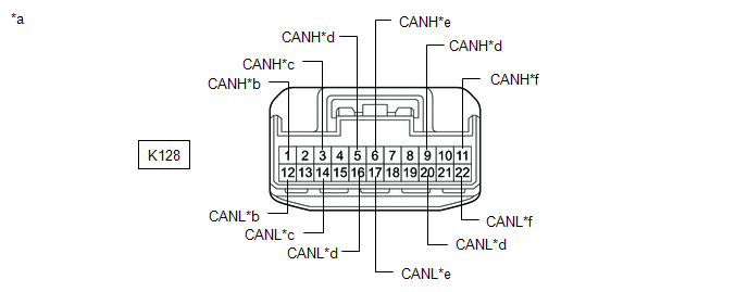
(2) Check the connection diagram of the components which are connected to the No. 4 CAN junction connector.
|
Terminal No. (Symbol) |
Wiring Color |
Connected to |
|---|---|---|
|
K128-1 (CANH) |
B |
Radio and display receiver assembly (for Bus 3) |
|
K128-12 (CANL) |
W |
|
|
K128-3 (CANH) |
LG |
Option connector (bus buffer ECU) (for Bus 3) |
|
K128-14 (CANL) |
W |
|
|
K128-5 (CANH) |
G |
Hybrid vehicle control ECU assembly (for Bus 4) |
|
K128-16 (CANL) |
W |
|
|
K128-6 (CANH) |
R |
Airbag sensor assembly (for Bus 4) |
|
K128-17 (CANL) |
W |
|
|
K128-9 (CANH) |
L |
Hybrid vehicle control ECU assembly (for Bus 2) |
|
K128-20 (CANL) |
W |
|
|
K128-11 (CANH) |
G |
No. 2 CAN junction connector (for Bus 2) |
|
K128-22 (CANL) |
W |
NO. 5 CAN JUNCTION CONNECTOR
(a) Check the No. 5 CAN junction connector.
(1) Connection diagram
|
*a |
Front view of wire harness connector (to No. 5 CAN Junction Connector) |
*b |
to Central Gateway ECU (Network Gateway ECU) |
|
*c |
to Clearance Warning ECU Assembly (w/ Intelligent Clearance Sonar System) |
*d |
to Blind Spot Monitor Sensor RH (w/ Blind Spot Monitor System) |
|
*e |
to Rear Television Camera Assembly (w/ Parking Assist Monitor System or Panoramic View Monitor System) |
*f |
to No. 1 CAN Junction Connector |
|
*g |
to Television Camera Controller (w/ Panoramic View Monitor System) |
- |
- |
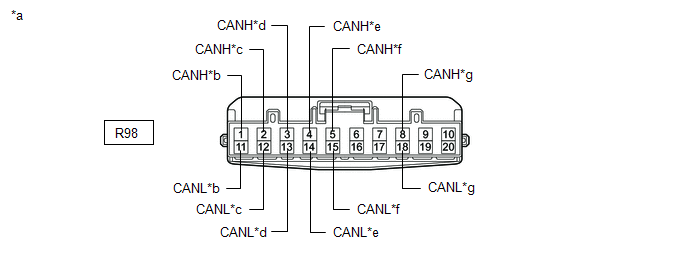
(2) Check the connection diagram of the components which are connected to the No. 5 CAN junction connector.
|
Terminal No. (Symbol) |
Wiring Color |
Connected to |
|---|---|---|
|
R98-1 (CANH) |
GR |
Central gateway ECU (network gateway ECU) (for Bus 1) |
|
R98-11 (CANL) |
W |
|
|
R98-2 (CANH) |
L |
Clearance warning ECU assembly*1 (for Bus 1) |
|
R98-12 (CANL) |
W |
|
|
R98-3 (CANH) |
BE |
Blind spot monitor sensor RH*2 (for Bus 1) |
|
R98-13 (CANL) |
W |
|
|
R98-4 (CANH) |
R |
Rear television camera assembly*3 (for Bus 1) |
|
R98-14 (CANL) |
W |
|
|
R98-5 (CANH) |
B |
No. 1 CAN junction connector (for Bus 1) |
|
R98-15 (CANL) |
W |
|
|
R98-8 (CANH) |
GR |
Television camera controller*4 (for Bus 1) |
|
R98-18 (CANL) |
W |
- *1: w/ Intelligent Clearance Sonar System
- *2: w/ Blind Spot Monitor System
- *3: w/ Parking Assist Monitor System or Panoramic View Monitor System
- *4: w/ Panoramic View Monitor System
NO. 1 JUNCTION CONNECTOR
(a) Check the No. 1 junction connector.
(1) Connection diagram
|
*a |
Front view of wire harness connector (to No. 1 Junction Connector) |
*b |
to No. 3 CAN Junction Connector |
|
*c |
to No. 2 Junction Connector |
- |
- |
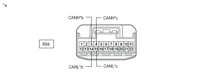
(2) Check the connection diagram of the components which are connected to the No. 1 junction connector.
|
Terminal No. (Symbol) |
Wiring Color |
Connected to |
|---|---|---|
|
R94-3 (CANH) |
B |
No. 3 CAN junction connector (for Bus 5) |
|
R94-14 (CANL) |
W |
|
|
R94-4 (CANH) |
L |
No. 2 junction connector (for Bus 5) |
|
R94-15 (CANL) |
W |
NO. 2 JUNCTION CONNECTOR
(a) Check the No. 2 junction connector.
(1) Connection diagram
|
*a |
Front view of wire harness connector (to No. 2 Junction Connector) |
*b |
to Central Gateway ECU (Network Gateway ECU) |
|
*c |
to No. 1 Junction Connector |
*d |
to Headlight ECU Sub-assembly RH (w/ AFS) |
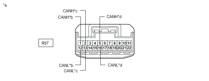
(2) Check the connection diagram of the components which are connected to the No. 2 junction connector.
|
Terminal No. (Symbol) |
Wiring Color |
Connected to |
|---|---|---|
|
R97-1 (CANH) |
G |
Central gateway ECU (network gateway ECU) (for Bus 5) |
|
R97-12 (CANL) |
W |
|
|
R97-2 (CANH) |
L |
No. 1 junction connector (for Bus 5) |
|
R97-13 (CANL) |
W |
|
|
R97-5 (CANH) |
G |
Headlight ECU sub-assembly RH* (for Bus 5) |
|
R97-16 (CANL) |
W |
- *: w/ AFS
NO. 3 JUNCTION CONNECTOR
(a) Check the No. 3 junction connector.
(1) Connection diagram
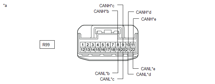
|
*a |
Front view of wire harness connector (to No. 3 Junction Connector) |
*b |
to Tire Pressure Warning ECU and Receiver (for Tire Pressure Warning System with Tire Inflation Pressure Display Function) |
|
*c |
to Occupant Detection ECU |
*d |
to Central Gateway ECU (Network Gateway ECU) |
|
*e |
to No. 2 CAN Junction Connector |
- |
- |
(2) Check the connection diagram of the components which are connected to the No. 3 junction connector.
|
Terminal No. (Symbol) |
Wiring Color |
Connected to |
|---|---|---|
|
R99-8 (CANH) |
L |
Tire pressure warning ECU and receiver* (for Bus 4) |
|
R99-19 (CANL) |
W |
|
|
R99-9 (CANH) |
GR |
Occupant detection ECU (for Bus 4) |
|
R99-20 (CANL) |
W |
|
|
R99-10 (CANH) |
G |
Central gateway ECU (network gateway ECU) (for Bus 4) |
|
R99-21 (CANL) |
W |
|
|
R99-11 (CANH) |
LG |
No. 2 CAN junction connector (for Bus 4) |
|
R99-22 (CANL) |
W |
- *: for Tire Pressure Warning System with Tire Inflation Pressure Display Function
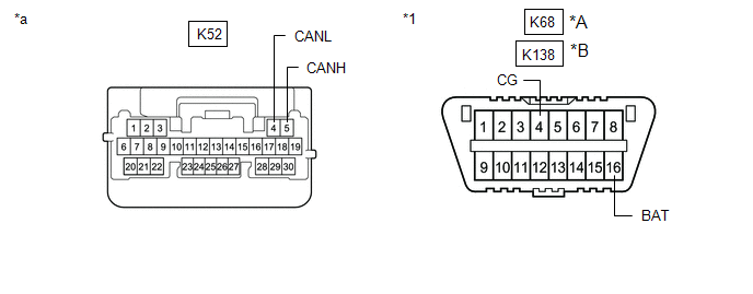
DLC3
(a) Disconnect the cable from the negative (-) auxiliary battery terminal.
(b) Measure the resistance according to the value(s) in the table below.
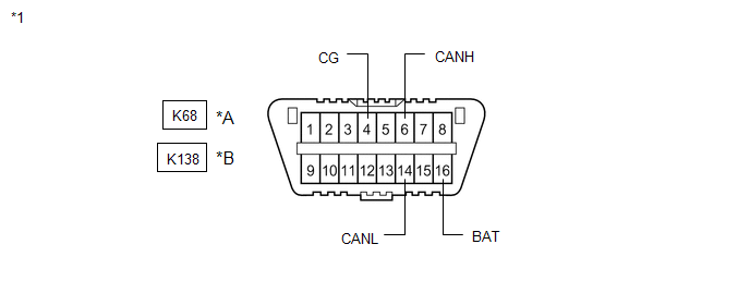
|
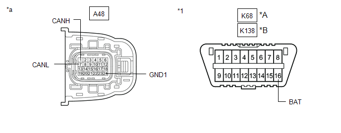
*A |
Before Aug. 2018 Production |
*B |
From Aug. 2018 Production |
|
*1 |
DLC3 |
- |
- |
Standard Resistance:
Before Aug. 2018 Production:
|
Terminal No. (Symbol) |
Wiring Color |
Terminal Description |
Condition |
Specified Condition |
|---|---|---|---|---|
|
K68-6 (CANH) - K68-14 (CANL) |
B - W |
HIGH-level CAN bus line - LOW-level CAN bus line |
Cable disconnected from negative (-) auxiliary battery terminal |
54 to 69 Ω |
|
K68-6 (CANH) - K68-4 (CG) |
B - W-B |
HIGH-level CAN bus line - Ground |
Cable disconnected from negative (-) auxiliary battery terminal |
200 Ω or higher |
|
K68-14 (CANL) - K68-4 (CG) |
W - W-B |
LOW-level CAN bus line - Ground |
Cable disconnected from negative (-) auxiliary battery terminal |
200 Ω or higher |
|
K68-6 (CANH) - K68-16 (BAT) |
B - R |
HIGH-level CAN bus line - Auxiliary battery positive (+) |
Cable disconnected from negative (-) auxiliary battery terminal |
6 kΩ or higher |
|
K68-14 (CANL) - K68-16 (BAT) |
W - R |
LOW-level CAN bus line - Auxiliary battery positive (+) |
Cable disconnected from negative (-) auxiliary battery terminal |
6 kΩ or higher |
From Aug. 2018 Production:
|
Terminal No. (Symbol) |
Wiring Color |
Terminal Description |
Condition |
Specified Condition |
|---|---|---|---|---|
|
K138-6 (CANH) - K138-14 (CANL) |
B - W |
HIGH-level CAN bus line - LOW-level CAN bus line |
Cable disconnected from negative (-) auxiliary battery terminal |
54 to 69 Ω |
|
K138-6 (CANH) - K138-4 (CG) |
B - W-B |
HIGH-level CAN bus line - Ground |
Cable disconnected from negative (-) auxiliary battery terminal |
200 Ω or higher |
|
K138-14 (CANL) - K138-4 (CG) |
W - W-B |
LOW-level CAN bus line - Ground |
Cable disconnected from negative (-) auxiliary battery terminal |
200 Ω or higher |
|
K138-6 (CANH) - K138-16 (BAT) |
B - R |
HIGH-level CAN bus line - Auxiliary battery positive (+) |
Cable disconnected from negative (-) auxiliary battery terminal |
6 kΩ or higher |
|
K138-14 (CANL) - K138-16 (BAT) |
W - R |
LOW-level CAN bus line - Auxiliary battery positive (+) |
Cable disconnected from negative (-) auxiliary battery terminal |
6 kΩ or higher |
CENTRAL GATEWAY ECU (NETWORK GATEWAY ECU)
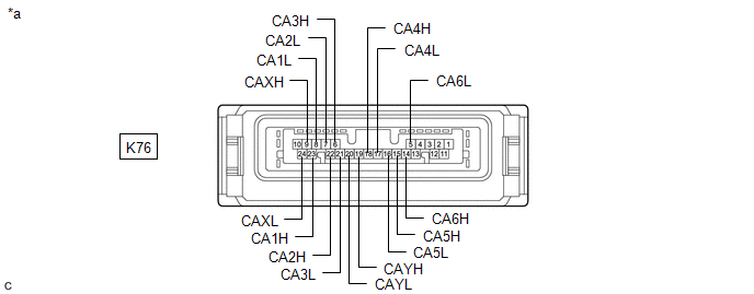
|
*a |
Component without harness connected (Central Gateway ECU (Network Gateway ECU)) |
- |
- |
(a) Disconnect the cable from the negative (-) auxiliary battery terminal.
(b) Disconnect the K76 central gateway ECU (network gateway ECU) connector.
(c) Measure the resistance according to the value(s) in the table below.
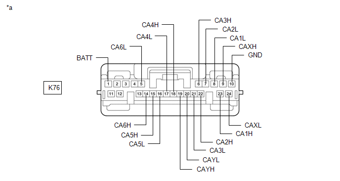
|
*a |
Front view of wire harness connector (to Central Gateway ECU (Network Gateway ECU)) |
- |
- |
Standard Resistance:
Diagnosis Bus Branch Lines (DLC3 - Central gateway ECU (network gateway ECU))
|
Terminal No. (Symbol) |
Wiring Color |
Terminal Description |
Condition |
Specified Condition |
|---|---|---|---|---|
|
K76-14 (CA6H) - K76-5 (CA6L) |
B - W |
HIGH-level CAN bus line - LOW-level CAN bus line |
Cable disconnected from negative (-) auxiliary battery terminal |
1 MΩ or higher |
|
K76-14 (CA6H) - K76-10 (GND) |
B - W-B |
HIGH-level CAN bus line - Ground |
Cable disconnected from negative (-) auxiliary battery terminal |
200 Ω or higher |
|
K76-5 (CA6L) - K76-10 (GND) |
W - W-B |
LOW-level CAN bus line - Ground |
Cable disconnected from negative (-) auxiliary battery terminal |
200 Ω or higher |
|
K76-14 (CA6H) - K76-1 (BATT) |
B - BE |
HIGH-level CAN bus line - Auxiliary battery positive (+) |
Cable disconnected from negative (-) auxiliary battery terminal |
6 kΩ or higher |
|
K76-5 (CA6L) - K76-1 (BATT) |
W - BE |
LOW-level CAN bus line - Auxiliary battery positive (+) |
Cable disconnected from negative (-) auxiliary battery terminal |
6 kΩ or higher |
Bus 1 Main Lines
|
Terminal No. (Symbol) |
Wiring Color |
Terminal Description |
Condition |
Specified Condition |
|---|---|---|---|---|
|
K76-23 (CA1H) - K76-9 (CAXH) |
B - BE |
HIGH-level CAN bus line - HIGH-level CAN bus line |
Cable disconnected from negative (-) auxiliary battery terminal |
Below 1 Ω |
|
K76-8 (CA1L) - K76-24 (CAXL) |
W - W |
LOW-level CAN bus line - LOW-level CAN bus line |
Cable disconnected from negative (-) auxiliary battery terminal |
Below 1 Ω |
|
K76-23 (CA1H) - K76-10 (GND) |
B - W-B |
HIGH-level CAN bus line - Ground |
Cable disconnected from negative (-) auxiliary battery terminal |
200 Ω or higher |
|
K76-8 (CA1L) - K76-10 (GND) |
W - W-B |
LOW-level CAN bus line - Ground |
Cable disconnected from negative (-) auxiliary battery terminal |
200 Ω or higher |
|
K76-23 (CA1H) - K76-1 (BATT) |
B - BE |
HIGH-level CAN bus line - Auxiliary battery positive (+) |
Cable disconnected from negative (-) auxiliary battery terminal |
6 kΩ or higher |
|
K76-8 (CA1L) - K76-1 (BATT) |
W - BE |
LOW-level CAN bus line - Auxiliary battery positive (+) |
Cable disconnected from negative (-) auxiliary battery terminal |
6 kΩ or higher |
Bus 2 Main Lines
|
Terminal No. (Symbol) |
Wiring Color |
Terminal Description |
Condition |
Specified Condition |
|---|---|---|---|---|
|
K76-18 (CA4H) - K76-17 (CA4L) |
SB - W |
HIGH-level CAN bus line - LOW-level CAN bus line |
Cable disconnected from negative (-) auxiliary battery terminal |
108 to 132 Ω |
|
K76-18 (CA4H) - K76-10 (GND) |
SB - W-B |
HIGH-level CAN bus line - Ground |
Cable disconnected from negative (-) auxiliary battery terminal |
200 Ω or higher |
|
K76-17 (CA4L) - K76-10 (GND) |
W - W-B |
LOW-level CAN bus line - Ground |
Cable disconnected from negative (-) auxiliary battery terminal |
200 Ω or higher |
|
K76-18 (CA4H) - K76-1 (BATT) |
SB - BE |
HIGH-level CAN bus line - Auxiliary battery positive (+) |
Cable disconnected from negative (-) auxiliary battery terminal |
6 kΩ or higher |
|
K76-17 (CA4L) - K76-1 (BATT) |
W - BE |
LOW-level CAN bus line - Auxiliary battery positive (+) |
Cable disconnected from negative (-) auxiliary battery terminal |
6 kΩ or higher |
Bus 3 Main Lines
|
Terminal No. (Symbol) |
Wiring Color |
Terminal Description |
Condition |
Specified Condition |
|---|---|---|---|---|
|
K76-6 (CA3H) - K76-19 (CAYH) |
L - GR |
HIGH-level CAN bus line - HIGH-level CAN bus line |
Cable disconnected from negative (-) auxiliary battery terminal |
Below 1 Ω |
|
K76-21 (CA3L) - K76-20 (CAYL) |
W - W |
LOW-level CAN bus line - LOW-level CAN bus line |
Cable disconnected from negative (-) auxiliary battery terminal |
Below 1 Ω |
|
K76-6 (CA3H) - K76-10 (GND) |
L - W-B |
HIGH-level CAN bus line - Ground |
Cable disconnected from negative (-) auxiliary battery terminal |
200 Ω or higher |
|
K76-21 (CA3L) - K76-10 (GND) |
W - W-B |
LOW-level CAN bus line - Ground |
Cable disconnected from negative (-) auxiliary battery terminal |
200 Ω or higher |
|
K76-6 (CA3H) - K76-1 (BATT) |
L - BE |
HIGH-level CAN bus line - Auxiliary battery positive (+) |
Cable disconnected from negative (-) auxiliary battery terminal |
6 kΩ or higher |
|
K76-21 (CA3L) - K76-1 (BATT) |
W - BE |
LOW-level CAN bus line - Auxiliary battery positive (+) |
Cable disconnected from negative (-) auxiliary battery terminal |
6 kΩ or higher |
Bus 4 Main Lines
|
Terminal No. (Symbol) |
Wiring Color |
Terminal Description |
Condition |
Specified Condition |
|---|---|---|---|---|
|
K76-22 (CA2H) - K76-7 (CA2L) |
G - W |
HIGH-level CAN bus line - LOW-level CAN bus line |
Cable disconnected from negative (-) auxiliary battery terminal |
108 to 132 Ω |
|
K76-22 (CA2H) - K76-10 (GND) |
G - W-B |
HIGH-level CAN bus line - Ground |
Cable disconnected from negative (-) auxiliary battery terminal |
200 Ω or higher |
|
K76-7 (CA2L) - K76-10 (GND) |
W - W-B |
LOW-level CAN bus line - Ground |
Cable disconnected from negative (-) auxiliary battery terminal |
200 Ω or higher |
|
K76-22 (CA2H) - K76-1 (BATT) |
G - BE |
HIGH-level CAN bus line - Auxiliary battery positive (+) |
Cable disconnected from negative (-) auxiliary battery terminal |
6 kΩ or higher |
|
K76-7 (CA2L) - K76-1 (BATT) |
W - BE |
LOW-level CAN bus line - Auxiliary battery positive (+) |
Cable disconnected from negative (-) auxiliary battery terminal |
6 kΩ or higher |
Bus 5 Main Lines
|
Terminal No. (Symbol) |
Wiring Color |
Terminal Description |
Condition |
Specified Condition |
|---|---|---|---|---|
|
K76-15 (CA5H) - K76-16 (CA5L) |
LG - W |
HIGH-level CAN bus line - LOW-level CAN bus line |
Cable disconnected from negative (-) auxiliary battery terminal |
108 to 132 Ω |
|
K76-15 (CA5H) - K76-10 (GND) |
LG - W-B |
HIGH-level CAN bus line - Ground |
Cable disconnected from negative (-) auxiliary battery terminal |
200 Ω or higher |
|
K76-16 (CA5L) - K76-10 (GND) |
W - W-B |
LOW-level CAN bus line - Ground |
Cable disconnected from negative (-) auxiliary battery terminal |
200 Ω or higher |
|
K76-15 (CA5H) - K76-1 (BATT) |
LG - BE |
HIGH-level CAN bus line - Auxiliary battery positive (+) |
Cable disconnected from negative (-) auxiliary battery terminal |
6 kΩ or higher |
|
K76-16 (CA5L) - K76-1 (BATT) |
W - BE |
LOW-level CAN bus line - Auxiliary battery positive (+) |
Cable disconnected from negative (-) auxiliary battery terminal |
6 kΩ or higher |
STEERING SENSOR
|
*a |
Component without harness connected (Steering Sensor) |
- |
- |
(a) Disconnect the cable from the negative (-) auxiliary battery terminal.
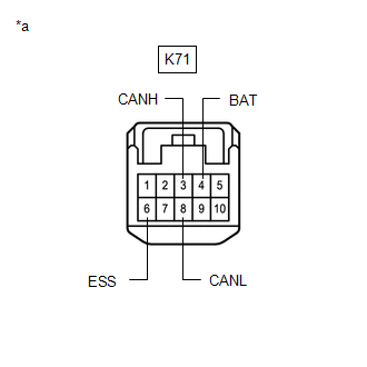
(b) Disconnect the K71 steering sensor connector.
(c) Measure the resistance according to the value(s) in the table below.
|
*a |
Front view of wire harness connector (to Steering Sensor) |
Standard Resistance:
|
Terminal No. (Symbol) |
Wiring Color |
Terminal Description |
Condition |
Specified Condition |
|---|---|---|---|---|
|
K71-3 (CANH) - K71-8 (CANL) |
G - W |
HIGH-level CAN bus line - LOW-level CAN bus line |
Cable disconnected from negative (-) auxiliary battery terminal |
54 to 69 Ω |
|
K71-3 (CANH) - K71-6 (ESS) |
G - W-B |
HIGH-level CAN bus line - Ground |
Cable disconnected from negative (-) auxiliary battery terminal |
200 Ω or higher |
|
K71-8 (CANL) - K71-6 (ESS) |
W - W-B |
LOW-level CAN bus line - Ground |
Cable disconnected from negative (-) auxiliary battery terminal |
200 Ω or higher |
|
K71-3 (CANH) - K71-4 (BAT) |
G - GR |
HIGH-level CAN bus line - Auxiliary battery positive (+) |
Cable disconnected from negative (-) auxiliary battery terminal |
6 kΩ or higher |
|
K71-8 (CANL) - K71-4 (BAT) |
W - GR |
LOW-level CAN bus line - Auxiliary battery positive (+) |
Cable disconnected from negative (-) auxiliary battery terminal |
6 kΩ or higher |
HYBRID VEHICLE CONTROL ECU ASSEMBLY
Refer to Terminals of ECU.
-
for Nickel Metal Hydride Battery
Click here
-
for Lithium-ion Battery
Click here
(a) Disconnect the cable from the negative (-) auxiliary battery terminal.
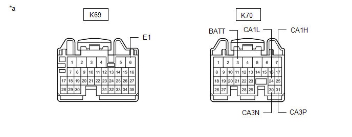
(b) Disconnect the K69 and K70 hybrid vehicle control ECU assembly connectors.
(c) Measure the resistance according to the value(s) in the table below.
|
*a |
Front view of wire harness connector (to Hybrid Vehicle Control ECU Assembly) |
- |
- |
Standard Resistance:
Bus 2 Branch Lines
|
Terminal No. (Symbol) |
Wiring Color |
Terminal Description |
Condition |
Specified Condition |
|---|---|---|---|---|
|
K70-25 (CA1H) - K70-24 (CA1L) |
L - W |
HIGH-level CAN bus line - LOW-level CAN bus line |
Cable disconnected from negative (-) auxiliary battery terminal |
54 to 69 Ω |
|
K70-25 (CA1H) - K69-6 (E1) |
L - W-B |
HIGH-level CAN bus line - Ground |
Cable disconnected from negative (-) auxiliary battery terminal |
200 Ω or higher |
|
K70-24 (CA1L) - K69-6 (E1) |
W - W-B |
LOW-level CAN bus line - Ground |
Cable disconnected from negative (-) auxiliary battery terminal |
200 Ω or higher |
|
K70-25 (CA1H) - K70-3 (BATT) |
L - B |
HIGH-level CAN bus line - Auxiliary battery positive (+) |
Cable disconnected from negative (-) auxiliary battery terminal |
6 kΩ or higher |
|
K70-24 (CA1L) - K70-3 (BATT) |
W - B |
LOW-level CAN bus line - Auxiliary battery positive (+) |
Cable disconnected from negative (-) auxiliary battery terminal |
6 kΩ or higher |
Bus 4 Branch Lines
|
Terminal No. (Symbol) |
Wiring Color |
Terminal Description |
Condition |
Specified Condition |
|---|---|---|---|---|
|
K70-31 (CA3P) - K70-30 (CA3N) |
G - W |
HIGH-level CAN bus line - LOW-level CAN bus line |
Cable disconnected from negative (-) auxiliary battery terminal |
54 to 69 Ω |
|
K70-31 (CA3P) - K69-6 (E1) |
G - W-B |
HIGH-level CAN bus line - Ground |
Cable disconnected from negative (-) auxiliary battery terminal |
200 Ω or higher |
|
K70-30 (CA3N) - K69-6 (E1) |
W - W-B |
LOW-level CAN bus line - Ground |
Cable disconnected from negative (-) auxiliary battery terminal |
200 Ω or higher |
|
K70-31 (CA3P) - K70-3 (BATT) |
G - B |
HIGH-level CAN bus line - Auxiliary battery positive (+) |
Cable disconnected from negative (-) auxiliary battery terminal |
6 kΩ or higher |
|
K70-30 (CA3N) - K70-3 (BATT) |
W - B |
LOW-level CAN bus line - Auxiliary battery positive (+) |
Cable disconnected from negative (-) auxiliary battery terminal |
6 kΩ or higher |
INVERTER WITH CONVERTER ASSEMBLY
Refer to Terminals of ECU.
-
for Nickel Metal Hydride Battery
Click here
-
for Lithium-ion Battery
Click here
(a) Disconnect the cable from the negative (-) auxiliary battery terminal.
(b) Disconnect the A48 inverter with converter assembly connector.
(c) Measure the resistance according to the value(s) in the table below.
|
*A |
Before Aug. 2018 Production |
*B |
From Aug. 2018 Production |
|
*1 |
DLC3 |
- |
- |
|
*a |
Front view of wire harness connector (to Inverter with Converter Assembly) |
- |
- |
Standard Resistance:
Before Aug. 2018 Production:
|
Terminal No. (Symbol) |
Wiring Color |
Terminal Description |
Condition |
Specified Condition |
|---|---|---|---|---|
|
A48-1 (CANH) - A48-7 (CANL) |
V - W |
HIGH-level CAN bus line - LOW-level CAN bus line |
Cable disconnected from negative (-) auxiliary battery terminal |
54 to 69 Ω |
|
A48-1 (CANH) - A48-24 (GND1) |
V - W-B |
HIGH-level CAN bus line - Ground |
Cable disconnected from negative (-) auxiliary battery terminal |
200 Ω or higher |
|
A48-7 (CANL) - A48-24 (GND1) |
W - W-B |
LOW-level CAN bus line - Ground |
Cable disconnected from negative (-) auxiliary battery terminal |
200 Ω or higher |
|
A48-1 (CANH) - K68-16 (BAT) |
V - R |
HIGH-level CAN bus line - Auxiliary battery positive (+) |
Cable disconnected from negative (-) auxiliary battery terminal |
6 kΩ or higher |
|
A48-7 (CANL) - K68-16 (BAT) |
W - R |
LOW-level CAN bus line - Auxiliary battery positive (+) |
Cable disconnected from negative (-) auxiliary battery terminal |
6 kΩ or higher |
From Aug. 2018 Production:
|
Terminal No. (Symbol) |
Wiring Color |
Terminal Description |
Condition |
Specified Condition |
|---|---|---|---|---|
|
A48-1 (CANH) - A48-7 (CANL) |
V - W |
HIGH-level CAN bus line - LOW-level CAN bus line |
Cable disconnected from negative (-) auxiliary battery terminal |
54 to 69 Ω |
|
A48-1 (CANH) - A48-24 (GND1) |
V - W-B |
HIGH-level CAN bus line - Ground |
Cable disconnected from negative (-) auxiliary battery terminal |
200 Ω or higher |
|
A48-7 (CANL) - A48-24 (GND1) |
W - W-B |
LOW-level CAN bus line - Ground |
Cable disconnected from negative (-) auxiliary battery terminal |
200 Ω or higher |
|
A48-1 (CANH) - K138-16 (BAT) |
V - R |
HIGH-level CAN bus line - Auxiliary battery positive (+) |
Cable disconnected from negative (-) auxiliary battery terminal |
6 kΩ or higher |
|
A48-7 (CANL) - K138-16 (BAT) |
W - R |
LOW-level CAN bus line - Auxiliary battery positive (+) |
Cable disconnected from negative (-) auxiliary battery terminal |
6 kΩ or higher |
BATTERY ECU ASSEMBLY (for Lithium-ion Battery)
Refer to Terminals of ECU.
Click here
(a) Disconnect the cable from the negative (-) auxiliary battery terminal.
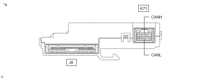
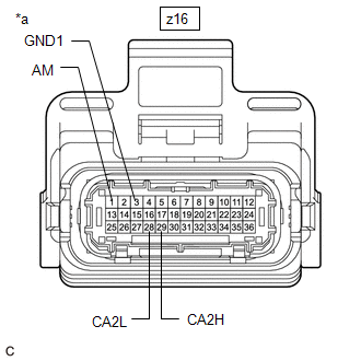
(b) Disconnect the z16 battery ECU assembly connector.
(c) Measure the resistance according to the value(s) in the table below.
|
*a |
Front view of wire harness connector (to Battery ECU Assembly) |
Standard Resistance:
|
Terminal No. (Symbol) |
Wiring Color |
Terminal Description |
Condition |
Specified Condition |
|---|---|---|---|---|
|
z16-29 (CA2H) - z16-28 (CA2L) |
R - W |
HIGH-level CAN bus line - LOW-level CAN bus line |
Cable disconnected from negative (-) auxiliary battery terminal |
54 to 69 Ω |
|
z16-29 (CA2H) - z16-3 (GND1) |
R - GR |
HIGH-level CAN bus line - Ground |
Cable disconnected from negative (-) auxiliary battery terminal |
200 Ω or higher |
|
z16-28 (CA2L) - z16-3 (GND1) |
W - GR |
LOW-level CAN bus line - Ground |
Cable disconnected from negative (-) auxiliary battery terminal |
200 Ω or higher |
|
z16-29 (CA2H) - z16-1 (AM) |
R - BR |
HIGH-level CAN bus line - Auxiliary battery positive (+) |
Cable disconnected from negative (-) auxiliary battery terminal |
6 kΩ or higher |
|
z16-28 (CA2L) - z16-1 (AM) |
W - BR |
LOW-level CAN bus line - Auxiliary battery positive (+) |
Cable disconnected from negative (-) auxiliary battery terminal |
6 kΩ or higher |
ECM
Refer to Terminals of ECU.
Click here
(a) Disconnect the cable from the negative (-) auxiliary battery terminal.
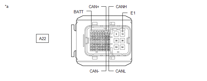
(b) Disconnect the A22 ECM connector.
(c) Measure the resistance according to the value(s) in the table below.
|
*a |
Front view of wire harness connector (to ECM) |
- |
- |
Standard Resistance:
Bus 2 Main Lines
|
Terminal No. (Symbol) |
Wiring Color |
Terminal Description |
Condition |
Specified Condition |
|---|---|---|---|---|
|
A22-8 (CANH) - A22-18 (CANL) |
B - W |
HIGH-level CAN bus line - LOW-level CAN bus line |
Cable disconnected from negative (-) auxiliary battery terminal |
108 to 132 Ω |
|
A22-8 (CANH) - A22-10 (E1) |
B - W-B |
HIGH-level CAN bus line - Ground |
Cable disconnected from negative (-) auxiliary battery terminal |
200 Ω or higher |
|
A22-18 (CANL) - A22-10 (E1) |
W - W-B |
LOW-level CAN bus line - Ground |
Cable disconnected from negative (-) auxiliary battery terminal |
200 Ω or higher |
|
A22-8 (CANH) - A22-1 (BATT) |
B - G |
HIGH-level CAN bus line - Auxiliary battery positive (+) |
Cable disconnected from negative (-) auxiliary battery terminal |
6 kΩ or higher |
|
A22-18 (CANL) - A22-1 (BATT) |
W - G |
LOW-level CAN bus line - Auxiliary battery positive (+) |
Cable disconnected from negative (-) auxiliary battery terminal |
6 kΩ or higher |
Bus 4 Branch Lines
|
Terminal No. (Symbol) |
Wiring Color |
Terminal Description |
Condition |
Specified Condition |
|---|---|---|---|---|
|
A22-7 (CAN+) - A22-17 (CAN-) |
P - W |
HIGH-level CAN bus line - LOW-level CAN bus line |
Cable disconnected from negative (-) auxiliary battery terminal |
54 to 69 Ω |
|
A22-7 (CAN+) - A22-10 (E1) |
P - W-B |
HIGH-level CAN bus line - Ground |
Cable disconnected from negative (-) auxiliary battery terminal |
200 Ω or higher |
|
A22-17 (CAN-) - A22-10 (E1) |
W - W-B |
LOW-level CAN bus line - Ground |
Cable disconnected from negative (-) auxiliary battery terminal |
200 Ω or higher |
|
A22-7 (CAN+) - A22-1 (BATT) |
P - G |
HIGH-level CAN bus line - Auxiliary battery positive (+) |
Cable disconnected from negative (-) auxiliary battery terminal |
6 kΩ or higher |
|
A22-17 (CAN-) - A22-1 (BATT) |
W - G |
LOW-level CAN bus line - Auxiliary battery positive (+) |
Cable disconnected from negative (-) auxiliary battery terminal |
6 kΩ or higher |
COMBINATION METER ASSEMBLY
Refer to Terminals of ECU.
Click here
(a) Disconnect the cable from the negative (-) auxiliary battery terminal.
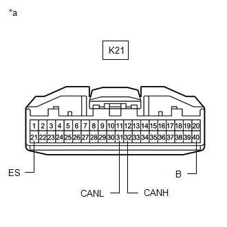
(b) Disconnect the K21 combination meter assembly connector.
(c) Measure the resistance according to the value(s) in the table below.
|
*a |
Front view of wire harness connector (to Combination Meter Assembly) |
Standard Resistance:
|
Terminal No. (Symbol) |
Wiring Color |
Terminal Description |
Condition |
Specified Condition |
|---|---|---|---|---|
|
K21-32 (CANH) - K21-31 (CANL) |
B - W |
HIGH-level CAN bus line - LOW-level CAN bus line |
Cable disconnected from negative (-) auxiliary battery terminal |
108 to 132 Ω |
|
K21-32 (CANH) - K21-21 (ES) |
B - W-B |
HIGH-level CAN bus line - Ground |
Cable disconnected from negative (-) auxiliary battery terminal |
200 Ω or higher |
|
K21-31 (CANL) - K21-21 (ES) |
W - W-B |
LOW-level CAN bus line - Ground |
Cable disconnected from negative (-) auxiliary battery terminal |
200 Ω or higher |
|
K21-32 (CANH) - K21-40 (B) |
B - LA-B |
HIGH-level CAN bus line - Auxiliary battery positive (+) |
Cable disconnected from negative (-) auxiliary battery terminal |
6 kΩ or higher |
|
K21-31 (CANL) - K21-40 (B) |
W - LA-B |
LOW-level CAN bus line - Auxiliary battery positive (+) |
Cable disconnected from negative (-) auxiliary battery terminal |
6 kΩ or higher |
BRAKE BOOSTER WITH MASTER CYLINDER ASSEMBLY
Refer to Terminals of ECU.
Click here
(a) Disconnect the cable from the negative (-) auxiliary battery terminal.
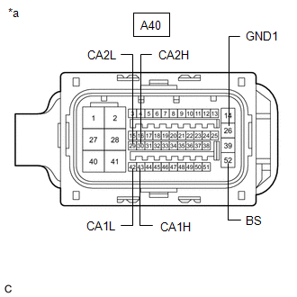
(b) Disconnect the A40 brake booster with master cylinder assembly connector.
(c) Measure the resistance according to the value(s) in the table below.
Standard Resistance:
Bus 2 Branch Lines
|
Terminal No. (Symbol) |
Wiring Color |
Terminal Description |
Condition |
Specified Condition |
|---|---|---|---|---|
|
A40-30 (CA2H) - A40-29 (CA2L) |
LG - W |
HIGH-level CAN bus line - LOW-level CAN bus line |
Cable disconnected from negative (-) auxiliary battery terminal |
54 to 69 Ω |
|
A40-30 (CA2H) - A40-26 (GND1) |
LG - LA |
HIGH-level CAN bus line - Ground |
Cable disconnected from negative (-) auxiliary battery terminal |
200 Ω or higher |
|
A40-29 (CA2L) - A40-26 (GND1) |
W - LA |
LOW-level CAN bus line - Ground |
Cable disconnected from negative (-) auxiliary battery terminal |
200 Ω or higher |
|
A40-30 (CA2H) - A40-52 (BS) |
LG - LG |
HIGH-level CAN bus line - Auxiliary battery positive (+) |
Cable disconnected from negative (-) auxiliary battery terminal |
6 kΩ or higher |
|
A40-29 (CA2L) - A40-52 (BS) |
W - LG |
LOW-level CAN bus line - Auxiliary battery positive (+) |
Cable disconnected from negative (-) auxiliary battery terminal |
6 kΩ or higher |
Bus 4 Branch Lines
|
Terminal No. (Symbol) |
Wiring Color |
Terminal Description |
Condition |
Specified Condition |
|---|---|---|---|---|
|
A40-43 (CA1H) - A40-42 (CA1L) |
Y - W |
HIGH-level CAN bus line - LOW-level CAN bus line |
Cable disconnected from negative (-) auxiliary battery terminal |
54 to 69 Ω |
|
A40-43 (CA1H) - A40-26 (GND1) |
Y - LA |
HIGH-level CAN bus line - Ground |
Cable disconnected from negative (-) auxiliary battery terminal |
200 Ω or higher |
|
A40-42 (CA1L) - A40-26 (GND1) |
W - LA |
LOW-level CAN bus line - Ground |
Cable disconnected from negative (-) auxiliary battery terminal |
200 Ω or higher |
|
A40-43 (CA1H) - A40-52 (BS) |
Y - LG |
HIGH-level CAN bus line - Auxiliary battery positive (+) |
Cable disconnected from negative (-) auxiliary battery terminal |
6 kΩ or higher |
|
A40-42 (CA1L) - A40-52 (BS) |
W - LG |
LOW-level CAN bus line - Auxiliary battery positive (+) |
Cable disconnected from negative (-) auxiliary battery terminal |
6 kΩ or higher |
|
*a |
Front view of wire harness connector (to Brake Booster with Master Cylinder Assembly) |
MAIN BODY ECU (MULTIPLEX NETWORK BODY ECU)
Refer to Terminals of ECU.
Click here
(a) Disconnect the cable from the negative (-) auxiliary battery terminal.
(b) Disconnect the K52 main body ECU (multiplex network body ECU) connector.
(c) Measure the resistance according to the value(s) in the table below.
|
*A |
Before Aug. 2018 Production |
*B |
From Aug. 2018 Production |
|
*1 |
DLC3 |
- |
- |
|
*a |
Front view of wire harness connector (to Main Body ECU (Multiplex Network Body ECU)) |
- |
- |
Standard Resistance:
Before Aug. 2018 Production:
|
Terminal No. (Symbol) |
Wiring Color |
Terminal Description |
Condition |
Specified Condition |
|---|---|---|---|---|
|
K52-5 (CANH) - K52-4 (CANL) |
BE - W |
HIGH-level CAN bus line - LOW-level CAN bus line |
Cable disconnected from negative (-) auxiliary battery terminal |
54 to 69 Ω |
|
K52-5 (CANH) - K68-4 (CG) |
BE - W-B |
HIGH-level CAN bus line - Ground |
Cable disconnected from negative (-) auxiliary battery terminal |
200 Ω or higher |
|
K52-4 (CANL) - K68-4 (CG) |
W - W-B |
LOW-level CAN bus line - Ground |
Cable disconnected from negative (-) auxiliary battery terminal |
200 Ω or higher |
|
K52-5 (CANH) - K68-16 (BAT) |
BE - R |
HIGH-level CAN bus line - Auxiliary battery positive (+) |
Cable disconnected from negative (-) auxiliary battery terminal |
6 kΩ or higher |
|
K52-4 (CANL) - K68-16 (BAT) |
W - R |
LOW-level CAN bus line - Auxiliary battery positive (+) |
Cable disconnected from negative (-) auxiliary battery terminal |
6 kΩ or higher |
From Aug. 2018 Production:
|
Terminal No. (Symbol) |
Wiring Color |
Terminal Description |
Condition |
Specified Condition |
|---|---|---|---|---|
|
K52-5 (CANH) - K52-4 (CANL) |
BE - W |
HIGH-level CAN bus line - LOW-level CAN bus line |
Cable disconnected from negative (-) auxiliary battery terminal |
54 to 69 Ω |
|
K52-5 (CANH) - K138-4 (CG) |
BE - W-B |
HIGH-level CAN bus line - Ground |
Cable disconnected from negative (-) auxiliary battery terminal |
200 Ω or higher |
|
K52-4 (CANL) - K138-4 (CG) |
W - W-B |
LOW-level CAN bus line - Ground |
Cable disconnected from negative (-) auxiliary battery terminal |
200 Ω or higher |
|
K52-5 (CANH) - K138-16 (BAT) |
BE - R |
HIGH-level CAN bus line - Auxiliary battery positive (+) |
Cable disconnected from negative (-) auxiliary battery terminal |
6 kΩ or higher |
|
K52-4 (CANL) - K138-16 (BAT) |
W - R |
LOW-level CAN bus line - Auxiliary battery positive (+) |
Cable disconnected from negative (-) auxiliary battery terminal |
6 kΩ or higher |
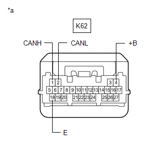
CERTIFICATION ECU (SMART KEY ECU ASSEMBLY)
Refer to Terminals of ECU.
Click here
(a) Disconnect the cable from the negative (-) auxiliary battery terminal.
(b) Disconnect the K62 certification ECU (smart key ECU assembly) connector.
(c) Measure the resistance according to the value(s) in the table below.
Standard Resistance:
|
Terminal No. (Symbol) |
Wiring Color |
Terminal Description |
Condition |
Specified Condition |
|---|---|---|---|---|
|
K62-1 (CANH) - K62-2 (CANL) |
G - W |
HIGH-level CAN bus line - LOW-level CAN bus line |
Cable disconnected from negative (-) auxiliary battery terminal |
54 to 69 Ω |
|
K62-1 (CANH) - K62-18 (E) |
G - W-B |
HIGH-level CAN bus line - Ground |
Cable disconnected from negative (-) auxiliary battery terminal |
200 Ω or higher |
|
K62-2 (CANL) - K62-18 (E) |
W - W-B |
LOW-level CAN bus line - Ground |
Cable disconnected from negative (-) auxiliary battery terminal |
200 Ω or higher |
|
K62-1 (CANH) - K62-4 (+B) |
G - W |
HIGH-level CAN bus line - Auxiliary battery positive (+) |
Cable disconnected from negative (-) auxiliary battery terminal |
6 kΩ or higher |
|
K62-2 (CANL) - K62-4 (+B) |
W - W |
LOW-level CAN bus line - Auxiliary battery positive (+) |
Cable disconnected from negative (-) auxiliary battery terminal |
6 kΩ or higher |
|
*a |
Front view of wire harness connector (to Certification ECU (Smart Key ECU Assembly)) |
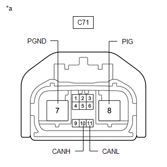
RACK AND PINION POWER STEERING GEAR ASSEMBLY
Refer to Terminals of ECU.
Click here
(a) Disconnect the cable from the negative (-) auxiliary battery terminal.
(b) Disconnect the C71 rack and pinion power steering gear assembly connector.
(c) Measure the resistance according to the value(s) in the table below.
|
*a |
Front view of wire harness connector (to Rack and Pinion Power Steering Gear Assembly) |
Standard Resistance:
|
Terminal No. (Symbol) |
Wiring Color |
Terminal Description |
Condition |
Specified Condition |
|---|---|---|---|---|
|
C71-10 (CANH) - C71-11 (CANL) |
G - W |
HIGH-level CAN bus line - LOW-level CAN bus line |
Cable disconnected from negative (-) auxiliary battery terminal |
54 to 69 Ω |
|
C71-10 (CANH) - C71-7 (PGND) |
G - B |
HIGH-level CAN bus line - Ground |
Cable disconnected from negative (-) auxiliary battery terminal |
200 Ω or higher |
|
C71-11 (CANL) - C71-7 (PGND) |
W - B |
LOW-level CAN bus line - Ground |
Cable disconnected from negative (-) auxiliary battery terminal |
200 Ω or higher |
|
C71-10 (CANH) - C71-8 (PIG) |
G - W |
HIGH-level CAN bus line - Auxiliary battery positive (+) |
Cable disconnected from negative (-) auxiliary battery terminal |
6 kΩ or higher |
|
C71-11 (CANL) - C71-8 (PIG) |
W - W |
LOW-level CAN bus line - Auxiliary battery positive (+) |
Cable disconnected from negative (-) auxiliary battery terminal |
6 kΩ or higher |
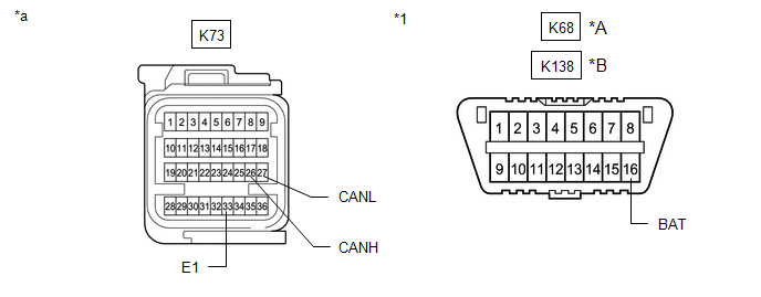
AIRBAG SENSOR ASSEMBLY
Refer to Terminals of ECU.
Click here
(a) Disconnect the cable from the negative (-) auxiliary battery terminal.
(b) Disconnect the K73 airbag sensor assembly connector.
(c) Measure the resistance according to the value(s) in the table below.
|
*A |
Before Aug. 2018 Production |
*B |
From Aug. 2018 Production |
|
*1 |
DLC3 |
- |
- |
|
*a |
Front view of wire harness connector (to Airbag Sensor Assembly) |
- |
- |
Standard Resistance:
Before Aug. 2018 Production:
|
Terminal No. (Symbol) |
Wiring Color |
Terminal Description |
Condition |
Specified Condition |
|---|---|---|---|---|
|
K73-26 (CANH) - K73-27 (CANL) |
R - W |
HIGH-level CAN bus line - LOW-level CAN bus line |
Cable disconnected from negative (-) auxiliary battery terminal |
108 to 132 Ω |
|
K73-26 (CANH) - K73-33 (E1) |
R - W-B |
HIGH-level CAN bus line - Ground |
Cable disconnected from negative (-) auxiliary battery terminal |
200 Ω or higher |
|
K73-27 (CANL) - K73-33 (E1) |
W - W-B |
LOW-level CAN bus line - Ground |
Cable disconnected from negative (-) auxiliary battery terminal |
200 Ω or higher |
|
K73-26 (CANH) - K68-16 (BAT) |
R - R |
HIGH-level CAN bus line - Auxiliary battery positive (+) |
Cable disconnected from negative (-) auxiliary battery terminal |
6 kΩ or higher |
|
K73-27 (CANL) - K68-16 (BAT) |
W - R |
LOW-level CAN bus line - Auxiliary battery positive (+) |
Cable disconnected from negative (-) auxiliary battery terminal |
6 kΩ or higher |
From Aug. 2018 Production:
|
Terminal No. (Symbol) |
Wiring Color |
Terminal Description |
Condition |
Specified Condition |
|---|---|---|---|---|
|
K73-26 (CANH) - K73-27 (CANL) |
R - W |
HIGH-level CAN bus line - LOW-level CAN bus line |
Cable disconnected from negative (-) auxiliary battery terminal |
108 to 132 Ω |
|
K73-26 (CANH) - K73-33 (E1) |
R - W-B |
HIGH-level CAN bus line - Ground |
Cable disconnected from negative (-) auxiliary battery terminal |
200 Ω or higher |
|
K73-27 (CANL) - K73-33 (E1) |
W - W-B |
LOW-level CAN bus line - Ground |
Cable disconnected from negative (-) auxiliary battery terminal |
200 Ω or higher |
|
K73-26 (CANH) - K138-16 (BAT) |
R - R |
HIGH-level CAN bus line - Auxiliary battery positive (+) |
Cable disconnected from negative (-) auxiliary battery terminal |
6 kΩ or higher |
|
K73-27 (CANL) - K138-16 (BAT) |
W - R |
LOW-level CAN bus line - Auxiliary battery positive (+) |
Cable disconnected from negative (-) auxiliary battery terminal |
6 kΩ or higher |
AIR CONDITIONING AMPLIFIER ASSEMBLY
Refer to Terminals of ECU.
Click here
(a) Disconnect the cable from the negative (-) auxiliary battery terminal.
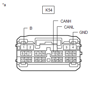
(b) Disconnect the K54 air conditioning amplifier assembly connector.
(c) Measure the resistance according to the value(s) in the table below.
Standard Resistance:
|
Terminal No. (Symbol) |
Wiring Color |
Terminal Description |
Condition |
Specified Condition |
|---|---|---|---|---|
|
K54-11 (CANH) - K54-12 (CANL) |
SB - W |
HIGH-level CAN bus line - LOW-level CAN bus line |
Cable disconnected from negative (-) auxiliary battery terminal |
54 to 69 Ω |
|
K54-11 (CANH) - K54-4 (GND) |
SB - W-B |
HIGH-level CAN bus line - Ground |
Cable disconnected from negative (-) auxiliary battery terminal |
200 Ω or higher |
|
K54-12 (CANL) - K54-4 (GND) |
W - W-B |
LOW-level CAN bus line - Ground |
Cable disconnected from negative (-) auxiliary battery terminal |
200 Ω or higher |
|
K54-11 (CANH) - K54-1 (B) |
SB - LA-B |
HIGH-level CAN bus line - Auxiliary battery positive (+) |
Cable disconnected from negative (-) auxiliary battery terminal |
6 kΩ or higher |
|
K54-12 (CANL) - K54-1 (B) |
W - LA-B |
LOW-level CAN bus line - Auxiliary battery positive (+) |
Cable disconnected from negative (-) auxiliary battery terminal |
6 kΩ or higher |
|
*a |
Front view of wire harness connector (to Air Conditioning Amplifier Assembly) |
RADIO AND DISPLAY RECEIVER ASSEMBLY
Refer to Terminals of ECU.
-
for Audio and Visual System
Click here
-
for Navigation System
Click here
(a) Disconnect the cable from the negative (-) auxiliary battery terminal.
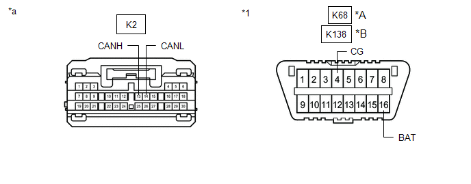
(b) Disconnect the K2 radio and display receiver assembly connector.
(c) Measure the resistance according to the value(s) in the table below.
|
*A |
Before Aug. 2018 Production |
*B |
From Aug. 2018 Production |
|
*1 |
DLC3 |
- |
- |
|
*a |
Front view of wire harness connector (to Radio and Display Receiver Assembly) |
- |
- |
Standard Resistance:
Before Aug. 2018 Production:
|
Terminal No. (Symbol) |
Wiring Color |
Terminal Description |
Condition |
Specified Condition |
|---|---|---|---|---|
|
K2-13 (CANH) - K2-14 (CANL) |
B - W |
HIGH-level CAN bus line - LOW-level CAN bus line |
Cable disconnected from negative (-) auxiliary battery terminal |
54 to 69 Ω |
|
K2-13 (CANH) - K68-4 (CG) |
B - W-B |
HIGH-level CAN bus line - Ground |
Cable disconnected from negative (-) auxiliary battery terminal |
200 Ω or higher |
|
K2-14 (CANL) - K68-4 (CG) |
W - W-B |
LOW-level CAN bus line - Ground |
Cable disconnected from negative (-) auxiliary battery terminal |
200 Ω or higher |
|
K2-13 (CANH) - K68-16 (BAT) |
B - R |
HIGH-level CAN bus line - Auxiliary battery positive (+) |
Cable disconnected from negative (-) auxiliary battery terminal |
6 kΩ or higher |
|
K2-14 (CANL) - K68-16 (BAT) |
W - R |
LOW-level CAN bus line - Auxiliary battery positive (+) |
Cable disconnected from negative (-) auxiliary battery terminal |
6 kΩ or higher |
From Aug. 2018 Production:
|
Terminal No. (Symbol) |
Wiring Color |
Terminal Description |
Condition |
Specified Condition |
|---|---|---|---|---|
|
K2-13 (CANH) - K2-14 (CANL) |
B - W |
HIGH-level CAN bus line - LOW-level CAN bus line |
Cable disconnected from negative (-) auxiliary battery terminal |
54 to 69 Ω |
|
K2-13 (CANH) - K138-4 (CG) |
B - W-B |
HIGH-level CAN bus line - Ground |
Cable disconnected from negative (-) auxiliary battery terminal |
200 Ω or higher |
|
K2-14 (CANL) - K138-4 (CG) |
W - W-B |
LOW-level CAN bus line - Ground |
Cable disconnected from negative (-) auxiliary battery terminal |
200 Ω or higher |
|
K2-13 (CANH) - K138-16 (BAT) |
B - R |
HIGH-level CAN bus line - Auxiliary battery positive (+) |
Cable disconnected from negative (-) auxiliary battery terminal |
6 kΩ or higher |
|
K2-14 (CANL) - K138-16 (BAT) |
W - R |
LOW-level CAN bus line - Auxiliary battery positive (+) |
Cable disconnected from negative (-) auxiliary battery terminal |
6 kΩ or higher |
BLIND SPOT MONITOR SENSOR RH (w/ Blind Spot Monitor System)
Refer to Terminals of ECU.
Click here
(a) Disconnect the cable from the negative (-) auxiliary battery terminal.
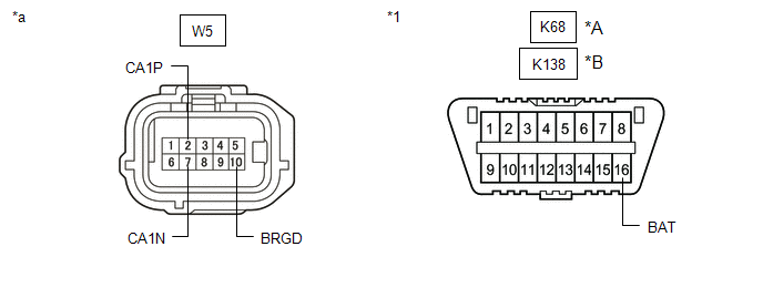
(b) Disconnect the W5 blind spot monitor sensor RH connector.
(c) Measure the resistance according to the value(s) in the table below.
|
*A |
Before Aug. 2018 Production |
*B |
From Aug. 2018 Production |
|
*1 |
DLC3 |
- |
- |
|
*a |
Front view of wire harness connector (to Blind Spot Monitor Sensor RH) |
- |
- |
Standard Resistance:
Before Aug. 2018 Production:
|
Terminal No. (Symbol) |
Wiring Color |
Terminal Description |
Condition |
Specified Condition |
|---|---|---|---|---|
|
W5-2 (CA1P) - W5-7 (CA1N) |
V - W |
HIGH-level CAN bus line - LOW-level CAN bus line |
Cable disconnected from negative (-) auxiliary battery terminal |
54 to 69 Ω |
|
W5-2 (CA1P) - W5-10 (BRGD) |
V - W-B |
HIGH-level CAN bus line - Ground |
Cable disconnected from negative (-) auxiliary battery terminal |
200 Ω or higher |
|
W5-7 (CA1N) - W5-10 (BRGD) |
W - W-B |
LOW-level CAN bus line - Ground |
Cable disconnected from negative (-) auxiliary battery terminal |
200 Ω or higher |
|
W5-2 (CA1P) - K68-16 (BAT) |
V - R |
HIGH-level CAN bus line - Auxiliary battery positive (+) |
Cable disconnected from negative (-) auxiliary battery terminal |
6 kΩ or higher |
|
W5-7 (CA1N) - K68-16 (BAT) |
W - R |
LOW-level CAN bus line - Auxiliary battery positive (+) |
Cable disconnected from negative (-) auxiliary battery terminal |
6 kΩ or higher |
From Aug. 2018 Production:
|
Terminal No. (Symbol) |
Wiring Color |
Terminal Description |
Condition |
Specified Condition |
|---|---|---|---|---|
|
W5-2 (CA1P) - W5-7 (CA1N) |
V - W |
HIGH-level CAN bus line - LOW-level CAN bus line |
Cable disconnected from negative (-) auxiliary battery terminal |
54 to 69 Ω |
|
W5-2 (CA1P) - W5-10 (BRGD) |
V - W-B |
HIGH-level CAN bus line - Ground |
Cable disconnected from negative (-) auxiliary battery terminal |
200 Ω or higher |
|
W5-7 (CA1N) - W5-10 (BRGD) |
W - W-B |
LOW-level CAN bus line - Ground |
Cable disconnected from negative (-) auxiliary battery terminal |
200 Ω or higher |
|
W5-2 (CA1P) - K138-16 (BAT) |
V - R |
HIGH-level CAN bus line - Auxiliary battery positive (+) |
Cable disconnected from negative (-) auxiliary battery terminal |
6 kΩ or higher |
|
W5-7 (CA1N) - K138-16 (BAT) |
W - R |
LOW-level CAN bus line - Auxiliary battery positive (+) |
Cable disconnected from negative (-) auxiliary battery terminal |
6 kΩ or higher |
FORWARD RECOGNITION CAMERA
Refer to Terminals of ECU.
Click here
(a) Disconnect the cable from the negative (-) auxiliary battery terminal.
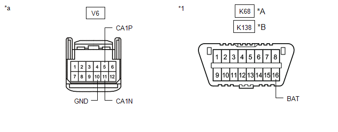
(b) Disconnect the V6 forward recognition camera connector.
(c) Measure the resistance according to the value(s) in the table below.
|
*A |
Before Aug. 2018 Production |
*B |
From Aug. 2018 Production |
|
*1 |
DLC3 |
- |
- |
|
*a |
Front view of wire harness connector (to Forward Recognition Camera) |
- |
- |
Standard Resistance:
Before Aug. 2018 Production:
|
Terminal No. (Symbol) |
Wiring Color |
Terminal Description |
Condition |
Specified Condition |
|---|---|---|---|---|
|
V6-5 (CA1P) - V6-11 (CA1N) |
L - W |
HIGH-level CAN bus line - LOW-level CAN bus line |
Cable disconnected from negative (-) auxiliary battery terminal |
54 to 69 Ω |
|
V6-5 (CA1P) - V6-10 (GND) |
L - W-B |
HIGH-level CAN bus line - Ground |
Cable disconnected from negative (-) auxiliary battery terminal |
200 Ω or higher |
|
V6-11 (CA1N) - V6-10 (GND) |
W - W-B |
LOW-level CAN bus line - Ground |
Cable disconnected from negative (-) auxiliary battery terminal |
200 Ω or higher |
|
V6-5 (CA1P) - K68-16 (BAT) |
L - R |
HIGH-level CAN bus line - Auxiliary battery positive (+) |
Cable disconnected from negative (-) auxiliary battery terminal |
6 kΩ or higher |
|
V6-11 (CA1N) - K68-16 (BAT) |
W - R |
LOW-level CAN bus line - Auxiliary battery positive (+) |
Cable disconnected from negative (-) auxiliary battery terminal |
6 kΩ or higher |
From Aug. 2018 Production:
|
Terminal No. (Symbol) |
Wiring Color |
Terminal Description |
Condition |
Specified Condition |
|---|---|---|---|---|
|
V6-5 (CA1P) - V6-11 (CA1N) |
L - W |
HIGH-level CAN bus line - LOW-level CAN bus line |
Cable disconnected from negative (-) auxiliary battery terminal |
54 to 69 Ω |
|
V6-5 (CA1P) - V6-10 (GND) |
L - W-B |
HIGH-level CAN bus line - Ground |
Cable disconnected from negative (-) auxiliary battery terminal |
200 Ω or higher |
|
V6-11 (CA1N) - V6-10 (GND) |
W - W-B |
LOW-level CAN bus line - Ground |
Cable disconnected from negative (-) auxiliary battery terminal |
200 Ω or higher |
|
V6-5 (CA1P) - K138-16 (BAT) |
L - R |
HIGH-level CAN bus line - Auxiliary battery positive (+) |
Cable disconnected from negative (-) auxiliary battery terminal |
6 kΩ or higher |
|
V6-11 (CA1N) - K138-16 (BAT) |
W - R |
LOW-level CAN bus line - Auxiliary battery positive (+) |
Cable disconnected from negative (-) auxiliary battery terminal |
6 kΩ or higher |
MILLIMETER WAVE RADAR SENSOR ASSEMBLY
Refer to Terminals of ECU.
Click here
(a) Disconnect the cable from the negative (-) auxiliary battery terminal.
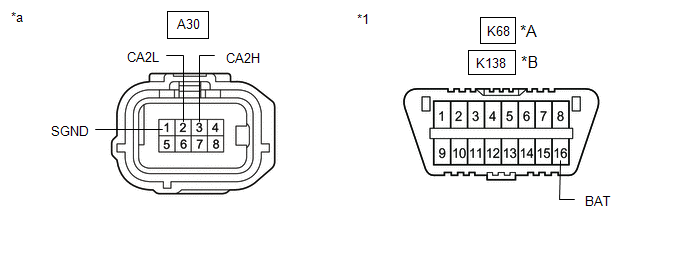
(b) Disconnect the A30 millimeter wave radar sensor assembly connector.
(c) Measure the resistance according to the value(s) in the table below.
|
*A |
Before Aug. 2018 Production |
*B |
From Aug. 2018 Production |
|
*1 |
DLC3 |
- |
- |
|
*a |
Front view of wire harness connector (to Millimeter Wave Radar Sensor Assembly) |
- |
- |
Standard Resistance:
Before Aug. 2018 Production:
|
Terminal No. (Symbol) |
Wiring Color |
Terminal Description |
Condition |
Specified Condition |
|---|---|---|---|---|
|
A30-3 (CA2H) - A30-2 (CA2L) |
R - W |
HIGH-level CAN bus line - LOW-level CAN bus line |
Cable disconnected from negative (-) auxiliary battery terminal |
54 to 69 Ω |
|
A30-3 (CA2H) - A30-1 (SGND) |
R - W-B |
HIGH-level CAN bus line - Ground |
Cable disconnected from negative (-) auxiliary battery terminal |
200 Ω or higher |
|
A30-2 (CA2L) - A30-1 (SGND) |
W - W-B |
LOW-level CAN bus line - Ground |
Cable disconnected from negative (-) auxiliary battery terminal |
200 Ω or higher |
|
A30-3 (CA2H) - K68-16 (BAT) |
R - R |
HIGH-level CAN bus line - Auxiliary battery positive (+) |
Cable disconnected from negative (-) auxiliary battery terminal |
6 kΩ or higher |
|
A30-2 (CA2L) - K68-16 (BAT) |
W - R |
LOW-level CAN bus line - Auxiliary battery positive (+) |
Cable disconnected from negative (-) auxiliary battery terminal |
6 kΩ or higher |
From Aug. 2018 Production:
|
Terminal No. (Symbol) |
Wiring Color |
Terminal Description |
Condition |
Specified Condition |
|---|---|---|---|---|
|
A30-3 (CA2H) - A30-2 (CA2L) |
R - W |
HIGH-level CAN bus line - LOW-level CAN bus line |
Cable disconnected from negative (-) auxiliary battery terminal |
54 to 69 Ω |
|
A30-3 (CA2H) - A30-1 (SGND) |
R - W-B |
HIGH-level CAN bus line - Ground |
Cable disconnected from negative (-) auxiliary battery terminal |
200 Ω or higher |
|
A30-2 (CA2L) - A30-1 (SGND) |
W - W-B |
LOW-level CAN bus line - Ground |
Cable disconnected from negative (-) auxiliary battery terminal |
200 Ω or higher |
|
A30-3 (CA2H) - K138-16 (BAT) |
R - R |
HIGH-level CAN bus line - Auxiliary battery positive (+) |
Cable disconnected from negative (-) auxiliary battery terminal |
6 kΩ or higher |
|
A30-2 (CA2L) - K138-16 (BAT) |
W - R |
LOW-level CAN bus line - Auxiliary battery positive (+) |
Cable disconnected from negative (-) auxiliary battery terminal |
6 kΩ or higher |
OCCUPANT DETECTION ECU
Refer to Terminals of ECU.
Click here
(a) Disconnect the cable from the negative (-) auxiliary battery terminal.
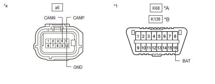
(b) Disconnect the a6 occupant detection ECU connector.
(c) Measure the resistance according to the value(s) in the table below.
|
*A |
Before Aug. 2018 Production |
*B |
From Aug. 2018 Production |
|
*1 |
DLC3 |
- |
- |
|
*a |
Front view of wire harness connector (to Occupant Detection ECU) |
- |
- |
Standard Resistance:
Before Aug. 2018 Production:
|
Terminal No. (Symbol) |
Wiring Color |
Terminal Description |
Condition |
Specified Condition |
|---|---|---|---|---|
|
a6-5 (CANP) - a6-4 (CANN) |
L - W |
HIGH-level CAN bus line - LOW-level CAN bus line |
Cable disconnected from negative (-) auxiliary battery terminal |
54 to 69 Ω |
|
a6-5 (CANP) - a6-10 (GND) |
L - W-B |
HIGH-level CAN bus line - Ground |
Cable disconnected from negative (-) auxiliary battery terminal |
200 Ω or higher |
|
a6-4 (CANN) - a6-10 (GND) |
W - W-B |
LOW-level CAN bus line - Ground |
Cable disconnected from negative (-) auxiliary battery terminal |
200 Ω or higher |
|
a6-5 (CANP) - K68-16 (BAT) |
L - R |
HIGH-level CAN bus line - Auxiliary battery positive (+) |
Cable disconnected from negative (-) auxiliary battery terminal |
6 kΩ or higher |
|
a6-4 (CANN) - K68-16 (BAT) |
W - R |
LOW-level CAN bus line - Auxiliary battery positive (+) |
Cable disconnected from negative (-) auxiliary battery terminal |
6 kΩ or higher |
From Aug. 2018 Production:
|
Terminal No. (Symbol) |
Wiring Color |
Terminal Description |
Condition |
Specified Condition |
|---|---|---|---|---|
|
a6-5 (CANP) - a6-4 (CANN) |
L - W |
HIGH-level CAN bus line - LOW-level CAN bus line |
Cable disconnected from negative (-) auxiliary battery terminal |
54 to 69 Ω |
|
a6-5 (CANP) - a6-10 (GND) |
L - W-B |
HIGH-level CAN bus line - Ground |
Cable disconnected from negative (-) auxiliary battery terminal |
200 Ω or higher |
|
a6-4 (CANN) - a6-10 (GND) |
W - W-B |
LOW-level CAN bus line - Ground |
Cable disconnected from negative (-) auxiliary battery terminal |
200 Ω or higher |
|
a6-5 (CANP) - K138-16 (BAT) |
L - R |
HIGH-level CAN bus line - Auxiliary battery positive (+) |
Cable disconnected from negative (-) auxiliary battery terminal |
6 kΩ or higher |
|
a6-4 (CANN) - K138-16 (BAT) |
W - R |
LOW-level CAN bus line - Auxiliary battery positive (+) |
Cable disconnected from negative (-) auxiliary battery terminal |
6 kΩ or higher |
OPTION CONNECTOR (BUS BUFFER ECU)
(a) Disconnect the cable from the negative (-) auxiliary battery terminal.
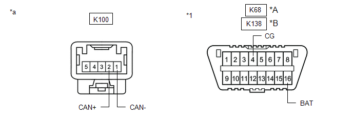
(b) Disconnect the K100 option connector (bus buffer ECU).
HINT:
Disconnect any CAN compatible optional devices from the option connector.
(c) Measure the resistance according to the value(s) in the table below.
|
*A |
Before Aug. 2018 Production |
*B |
From Aug. 2018 Production |
|
*1 |
DLC3 |
- |
- |
|
*a |
Front view of wire harness connector (to Option Connector (Bus Buffer ECU)) |
- |
- |
Standard Resistance:
Before Aug. 2018 Production:
|
Terminal No. (Symbol) |
Wiring Color |
Terminal Description |
Condition |
Specified Condition |
|---|---|---|---|---|
|
K100-2 (CAN+) - K100-1 (CAN-) |
LG - W |
HIGH-level CAN bus line - LOW-level CAN bus line |
Cable disconnected from negative (-) auxiliary battery terminal |
54 to 69 Ω |
|
K100-2 (CAN+) - K68-4 (CG) |
LG - W-B |
HIGH-level CAN bus line - Ground |
Cable disconnected from negative (-) auxiliary battery terminal |
200 Ω or higher |
|
K100-1 (CAN-) - K68-4 (CG) |
W - W-B |
LOW-level CAN bus line - Ground |
Cable disconnected from negative (-) auxiliary battery terminal |
200 Ω or higher |
|
K100-2 (CAN+) - K68-16 (BAT) |
LG - R |
HIGH-level CAN bus line - Auxiliary battery positive (+) |
Cable disconnected from negative (-) auxiliary battery terminal |
6 kΩ or higher |
|
K100-1 (CAN-) - K68-16 (BAT) |
W - R |
LOW-level CAN bus line - Auxiliary battery positive (+) |
Cable disconnected from negative (-) auxiliary battery terminal |
6 kΩ or higher |
From Aug. 2018 Production:
|
Terminal No. (Symbol) |
Wiring Color |
Terminal Description |
Condition |
Specified Condition |
|---|---|---|---|---|
|
K100-2 (CAN+) - K100-1 (CAN-) |
LG - W |
HIGH-level CAN bus line - LOW-level CAN bus line |
Cable disconnected from negative (-) auxiliary battery terminal |
54 to 69 Ω |
|
K100-2 (CAN+) - K138-4 (CG) |
LG - W-B |
HIGH-level CAN bus line - Ground |
Cable disconnected from negative (-) auxiliary battery terminal |
200 Ω or higher |
|
K100-1 (CAN-) - K138-4 (CG) |
W - W-B |
LOW-level CAN bus line - Ground |
Cable disconnected from negative (-) auxiliary battery terminal |
200 Ω or higher |
|
K100-2 (CAN+) - K138-16 (BAT) |
LG - R |
HIGH-level CAN bus line - Auxiliary battery positive (+) |
Cable disconnected from negative (-) auxiliary battery terminal |
6 kΩ or higher |
|
K100-1 (CAN-) - K138-16 (BAT) |
W - R |
LOW-level CAN bus line - Auxiliary battery positive (+) |
Cable disconnected from negative (-) auxiliary battery terminal |
6 kΩ or higher |
DCM (TELEMATICS TRANSCEIVER) (w/ Telematics Transceiver)
Refer to Terminals of ECU.
Click here
(a) Disconnect the cable from the negative (-) auxiliary battery terminal.
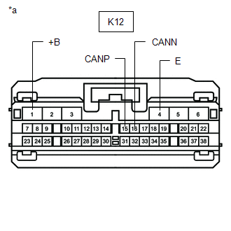
(b) Disconnect the K12 DCM (telematics transceiver) connector.
(c) Measure the resistance according to the value(s) in the table below.
Standard Resistance:
|
Terminal No. (Symbol) |
Wiring Color |
Terminal Description |
Condition |
Specified Condition |
|---|---|---|---|---|
|
K12-15 (CANP) - K12-16 (CANN) |
R - W |
HIGH-level CAN bus line - LOW-level CAN bus line |
Cable disconnected from negative (-) auxiliary battery terminal |
54 to 69 Ω |
|
K12-15 (CANP) - K12-4 (E) |
R - W-B |
HIGH-level CAN bus line - Ground |
Cable disconnected from negative (-) auxiliary battery terminal |
200 Ω or higher |
|
K12-16 (CANN) - K12-4 (E) |
W - W-B |
LOW-level CAN bus line - Ground |
Cable disconnected from negative (-) auxiliary battery terminal |
200 Ω or higher |
|
K12-15 (CANP) - K12-1 (+B) |
R - B |
HIGH-level CAN bus line - Auxiliary battery positive (+) |
Cable disconnected from negative (-) auxiliary battery terminal |
6 kΩ or higher |
|
K12-16 (CANN) - K12-1 (+B) |
W - B |
LOW-level CAN bus line - Auxiliary battery positive (+) |
Cable disconnected from negative (-) auxiliary battery terminal |
6 kΩ or higher |
|
*a |
Front view of wire harness connector (to DCM (Telematics Transceiver)) |
REAR TELEVISION CAMERA ASSEMBLY (w/ Parking Assist Monitor System or Panoramic View Monitor System)
Refer to Terminals of ECU.
-
for Parking Assist Monitor System
Click here
-
for Panoramic View Monitor System
Click here
(a) Disconnect the cable from the negative (-) auxiliary battery terminal.
(b) Disconnect the m1 rear television camera assembly connector.
(c) Measure the resistance according to the value(s) in the table below.
|
*A |
Before Aug. 2018 Production |
*B |
From Aug. 2018 Production |
|
*1 |
DLC3 |
- |
- |
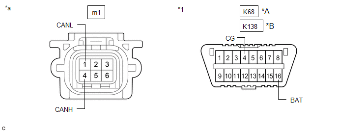
|
*a |
Front view of wire harness connector (to Rear Television Camera Assembly) |
- |
- |
Standard Resistance:
Before Aug. 2018 Production:
|
Terminal No. (Symbol) |
Wiring Color |
Terminal Description |
Condition |
Specified Condition |
|---|---|---|---|---|
|
m1-4 (CANH) - m1-1 (CANL) |
R - W |
HIGH-level CAN bus line - LOW-level CAN bus line |
Cable disconnected from negative (-) auxiliary battery terminal |
54 to 69 Ω |
|
m1-4 (CANH) - K68-4 (CG) |
R - W-B |
HIGH-level CAN bus line - Ground |
Cable disconnected from negative (-) auxiliary battery terminal |
200 Ω or higher |
|
m1-1 (CANL) - K68-4 (CG) |
W - W-B |
LOW-level CAN bus line - Ground |
Cable disconnected from negative (-) auxiliary battery terminal |
200 Ω or higher |
|
m1-4 (CANH) - K68-16 (BAT) |
R - R |
HIGH-level CAN bus line - Auxiliary battery positive (+) |
Cable disconnected from negative (-) auxiliary battery terminal |
6 kΩ or higher |
|
m1-1 (CANL) - K68-16 (BAT) |
W - R |
LOW-level CAN bus line - Auxiliary battery positive (+) |
Cable disconnected from negative (-) auxiliary battery terminal |
6 kΩ or higher |
From Jul. 2018 Production:
|
Terminal No. (Symbol) |
Wiring Color |
Terminal Description |
Condition |
Specified Condition |
|---|---|---|---|---|
|
m1-4 (CANH) - m1-1 (CANL) |
R - W |
HIGH-level CAN bus line - LOW-level CAN bus line |
Cable disconnected from negative (-) auxiliary battery terminal |
54 to 69 Ω |
|
m1-4 (CANH) - K138-4 (CG) |
R - W-B |
HIGH-level CAN bus line - Ground |
Cable disconnected from negative (-) auxiliary battery terminal |
200 Ω or higher |
|
m1-1 (CANL) - K138-4 (CG) |
W - W-B |
LOW-level CAN bus line - Ground |
Cable disconnected from negative (-) auxiliary battery terminal |
200 Ω or higher |
|
m1-4 (CANH) - K138-16 (BAT) |
R - R |
HIGH-level CAN bus line - Auxiliary battery positive (+) |
Cable disconnected from negative (-) auxiliary battery terminal |
6 kΩ or higher |
|
m1-1 (CANL) - K138-16 (BAT) |
W - R |
LOW-level CAN bus line - Auxiliary battery positive (+) |
Cable disconnected from negative (-) auxiliary battery terminal |
6 kΩ or higher |
TIRE PRESSURE WARNING ECU AND RECEIVER (for Tire Pressure Warning System with Tire Inflation Pressure Display Function)
Refer to Terminals of ECU.
Click here
(a) Disconnect the cable from the negative (-) auxiliary battery terminal.
(b) Disconnect the R9 tire pressure warning ECU and receiver connector.
(c) Measure the resistance according to the value(s) in the table below.
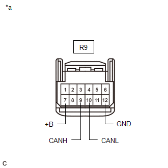
|
*a |
Front view of wire harness connector (to Tire Pressure Warning ECU and Receiver) |
Standard Resistance:
Before Aug. 2018 Production:
|
Terminal No. (Symbol) |
Wiring Color |
Terminal Description |
Condition |
Specified Condition |
|---|---|---|---|---|
|
R9-9 (CANH) - R9-10 (CANL) |
L - W |
HIGH-level CAN bus line - LOW-level CAN bus line |
Cable disconnected from negative (-) auxiliary battery terminal |
54 to 69 Ω |
|
R9-9 (CANH) - R9-12 (GND) |
L - BR |
HIGH-level CAN bus line - Ground |
Cable disconnected from negative (-) auxiliary battery terminal |
200 Ω or higher |
|
R9-10 (CANL) - R9-12 (GND) |
W - BR |
LOW-level CAN bus line - Ground |
Cable disconnected from negative (-) auxiliary battery terminal |
200 Ω or higher |
|
R9-9 (CANH) - R9-7 (+B) |
L - LA-R |
HIGH-level CAN bus line - Auxiliary battery positive (+) |
Cable disconnected from negative (-) auxiliary battery terminal |
6 kΩ or higher |
|
R9-10 (CANL) - R9-7 (+B) |
W - LA-R |
LOW-level CAN bus line - Auxiliary battery positive (+) |
Cable disconnected from negative (-) auxiliary battery terminal |
6 kΩ or higher |
From Aug. 2018 Production:
|
Terminal No. (Symbol) |
Wiring Color |
Terminal Description |
Condition |
Specified Condition |
|---|---|---|---|---|
|
R9-9 (CANH) - R9-10 (CANL) |
L - W |
HIGH-level CAN bus line - LOW-level CAN bus line |
Cable disconnected from negative (-) auxiliary battery terminal |
54 to 69 Ω |
|
R9-9 (CANH) - R9-12 (GND) |
L - W-B |
HIGH-level CAN bus line - Ground |
Cable disconnected from negative (-) auxiliary battery terminal |
200 Ω or higher |
|
R9-10 (CANL) - R9-12 (GND) |
W - W-B |
LOW-level CAN bus line - Ground |
Cable disconnected from negative (-) auxiliary battery terminal |
200 Ω or higher |
|
R9-9 (CANH) - R9-7 (+B) |
L - LA-R |
HIGH-level CAN bus line - Auxiliary battery positive (+) |
Cable disconnected from negative (-) auxiliary battery terminal |
6 kΩ or higher |
|
R9-10 (CANL) - R9-7 (+B) |
W - LA-R |
LOW-level CAN bus line - Auxiliary battery positive (+) |
Cable disconnected from negative (-) auxiliary battery terminal |
6 kΩ or higher |
BRAKE ACTUATOR ASSEMBLY
Refer to Terminals of ECU.
Click here
(a) Disconnect the cable from the negative (-) auxiliary battery terminal.
(b) Disconnect the A44 brake actuator assembly connector.
(c) Measure the resistance according to the value(s) in the table below.
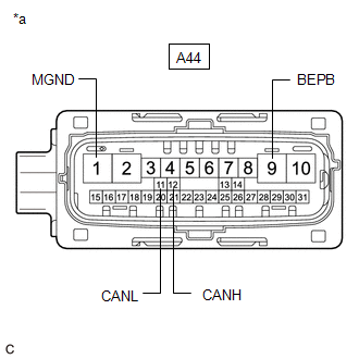
|
*a |
Front view of wire harness connector (to Brake Actuator Assembly) |
Standard Resistance:
|
Terminal No. (Symbol) |
Wiring Color |
Terminal Description |
Condition |
Specified Condition |
|---|---|---|---|---|
|
A44-12 (CANH) - A44-11 (CANL) |
B - W |
HIGH-level CAN bus line - LOW-level CAN bus line |
Cable disconnected from negative (-) auxiliary battery terminal |
54 to 69 Ω |
|
A44-12 (CANH) - A44-1 (MGND) |
B - W-B |
HIGH-level CAN bus line - Ground |
Cable disconnected from negative (-) auxiliary battery terminal |
200 Ω or higher |
|
A44-11 (CANL) - A44-1 (MGND) |
W - W-B |
LOW-level CAN bus line - Ground |
Cable disconnected from negative (-) auxiliary battery terminal |
200 Ω or higher |
|
A44-12 (CANH) - A44-9 (BEPB) |
B - R |
HIGH-level CAN bus line - Auxiliary battery positive (+) |
Cable disconnected from negative (-) auxiliary battery terminal |
6 kΩ or higher |
|
A44-11 (CANL) - A44-9 (BEPB) |
W - R |
LOW-level CAN bus line - Auxiliary battery positive (+) |
Cable disconnected from negative (-) auxiliary battery terminal |
6 kΩ or higher |
METER MIRROR SUB-ASSEMBLY (w/ Headup Display System)
Refer to Terminals of ECU.
Click here
(a) Disconnect the cable from the negative (-) auxiliary battery terminal.
(b) Disconnect the p1 meter mirror sub-assembly connector.
(c) Measure the resistance according to the value(s) in the table below.
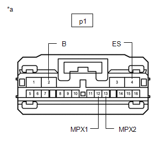
|
*a |
Front view of wire harness connector (to Meter Mirror Sub-assembly) |
Standard Resistance:
|
Terminal No. (Symbol) |
Wiring Color |
Terminal Description |
Condition |
Specified Condition |
|---|---|---|---|---|
|
p1-12 (MPX1) - p1-13 (MPX2) |
P - R |
HIGH-level CAN bus line - LOW-level CAN bus line |
Cable disconnected from negative (-) auxiliary battery terminal |
54 to 69 Ω |
|
p1-12 (MPX1) - p1-4 (ES) |
P - W-B |
HIGH-level CAN bus line - Ground |
Cable disconnected from negative (-) auxiliary battery terminal |
200 Ω or higher |
|
p1-13 (MPX2) - p1-4 (ES) |
R - W-B |
LOW-level CAN bus line - Ground |
Cable disconnected from negative (-) auxiliary battery terminal |
200 Ω or higher |
|
p1-12 (MPX1) - p1-2 (B) |
P - P |
HIGH-level CAN bus line - Auxiliary battery positive (+) |
Cable disconnected from negative (-) auxiliary battery terminal |
6 kΩ or higher |
|
p1-13 (MPX2) - p1-2 (B) |
R - P |
LOW-level CAN bus line - Auxiliary battery positive (+) |
Cable disconnected from negative (-) auxiliary battery terminal |
6 kΩ or higher |
HEADLIGHT ECU SUB-ASSEMBLY LH (w/ AFS)
Refer to Terminals of ECU.
Click here
(a) Disconnect the cable from the negative (-) auxiliary battery terminal.
(b) Disconnect the A10 headlight ECU sub-assembly LH connector.
(c) Measure the resistance according to the value(s) in the table below.
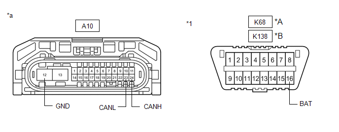
|
*A |
Before Aug. 2018 Production |
*B |
From Aug. 2018 Production |
|
*1 |
DLC3 |
- |
- |
|
*a |
Front view of wire harness connector (to Headlight ECU Sub-assembly LH) |
- |
- |
Standard Resistance:
Before Aug. 2018 Production:
|
Terminal No. (Symbol) |
Wiring Color |
Terminal Description |
Condition |
Specified Condition |
|---|---|---|---|---|
|
A10-24(CANH) - A10-23(CANL) |
P - W |
HIGH-level CAN bus line - LOW-level CAN bus line |
Cable disconnected from negative (-) auxiliary battery terminal |
54 to 69 Ω |
|
A10-24(CANH)) - A10-12 (GND) |
P - W-B |
HIGH-level CAN bus line - Ground |
Cable disconnected from negative (-) auxiliary battery terminal |
200 Ω or higher |
|
A10-23(CANL) - A10-12 (GND) |
W - W-B |
LOW-level CAN bus line - Ground |
Cable disconnected from negative (-) auxiliary battery terminal |
200 Ω or higher |
|
A10-24(CANH) - K68-16 (BAT) |
P - R |
HIGH-level CAN bus line - Auxiliary battery positive (+) |
Cable disconnected from negative (-) auxiliary battery terminal |
6 kΩ or higher |
|
A10-23(CANL) - K68-16 (BAT) |
W - R |
LOW-level CAN bus line - Auxiliary battery positive (+) |
Cable disconnected from negative (-) auxiliary battery terminal |
6 kΩ or higher |
From Aug. 2018 Production:
|
Terminal No. (Symbol) |
Wiring Color |
Terminal Description |
Condition |
Specified Condition |
|---|---|---|---|---|
|
A10-24(CANH) - A10-23(CANL) |
P - W |
HIGH-level CAN bus line - LOW-level CAN bus line |
Cable disconnected from negative (-) auxiliary battery terminal |
54 to 69 Ω |
|
A10-24(CANH)) - A10-12 (GND) |
P - W-B |
HIGH-level CAN bus line - Ground |
Cable disconnected from negative (-) auxiliary battery terminal |
200 Ω or higher |
|
A10-23(CANL) - A10-12 (GND) |
W - W-B |
LOW-level CAN bus line - Ground |
Cable disconnected from negative (-) auxiliary battery terminal |
200 Ω or higher |
|
A10-24(CANH) - K138-16 (BAT) |
P - R |
HIGH-level CAN bus line - Auxiliary battery positive (+) |
Cable disconnected from negative (-) auxiliary battery terminal |
6 kΩ or higher |
|
A10-23(CANL) - K138-16 (BAT) |
W - R |
LOW-level CAN bus line - Auxiliary battery positive (+) |
Cable disconnected from negative (-) auxiliary battery terminal |
6 kΩ or higher |
HEADLIGHT ECU SUB-ASSEMBLY RH (w/ AFS)
Refer to Terminals of ECU.
Click here
(a) Disconnect the cable from the negative (-) auxiliary battery terminal.
(b) Disconnect the A11 headlight ECU sub-assembly RH connector.
(c) Measure the resistance according to the value(s) in the table below.
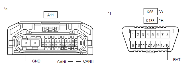
|
*A |
Before Aug. 2018 Production |
*B |
From Aug. 2018 Production |
|
*1 |
DLC3 |
- |
- |
|
*a |
Front view of wire harness connector (to Headlight ECU Sub-assembly RH) |
- |
- |
Standard Resistance:
Before Aug. 2018 Production:
|
Terminal No. (Symbol) |
Wiring Color |
Terminal Description |
Condition |
Specified Condition |
|---|---|---|---|---|
|
A11-24(CANH) - A11-23(CANL) |
L - W |
HIGH-level CAN bus line - LOW-level CAN bus line |
Cable disconnected from negative (-) auxiliary battery terminal |
54 to 69 Ω |
|
A11-24(CANH)) - A11-12 (GND) |
L - W-B |
HIGH-level CAN bus line - Ground |
Cable disconnected from negative (-) auxiliary battery terminal |
200 Ω or higher |
|
A11-23(CANL) - A11-12 (GND) |
W - W-B |
LOW-level CAN bus line - Ground |
Cable disconnected from negative (-) auxiliary battery terminal |
200 Ω or higher |
|
A11-24(CANH) - K68-16 (BAT) |
L - R |
HIGH-level CAN bus line - Auxiliary battery positive (+) |
Cable disconnected from negative (-) auxiliary battery terminal |
6 kΩ or higher |
|
A11-23(CANL) - K68-16 (BAT) |
W - R |
LOW-level CAN bus line - Auxiliary battery positive (+) |
Cable disconnected from negative (-) auxiliary battery terminal |
6 kΩ or higher |
From Aug. 2018 Production:
|
Terminal No. (Symbol) |
Wiring Color |
Terminal Description |
Condition |
Specified Condition |
|---|---|---|---|---|
|
A11-24(CANH) - A11-23(CANL) |
L - W |
HIGH-level CAN bus line - LOW-level CAN bus line |
Cable disconnected from negative (-) auxiliary battery terminal |
54 to 69 Ω |
|
A11-24(CANH)) - A11-12 (GND) |
L - W-B |
HIGH-level CAN bus line - Ground |
Cable disconnected from negative (-) auxiliary battery terminal |
200 Ω or higher |
|
A11-23(CANL) - A11-12 (GND) |
W - W-B |
LOW-level CAN bus line - Ground |
Cable disconnected from negative (-) auxiliary battery terminal |
200 Ω or higher |
|
A11-24(CANH) - K138-16 (BAT) |
L - R |
HIGH-level CAN bus line - Auxiliary battery positive (+) |
Cable disconnected from negative (-) auxiliary battery terminal |
6 kΩ or higher |
|
A11-23(CANL) - K138-16 (BAT) |
W - R |
LOW-level CAN bus line - Auxiliary battery positive (+) |
Cable disconnected from negative (-) auxiliary battery terminal |
6 kΩ or higher |
SWING GRILLE ACTUATOR ASSEMBLY
Refer to Terminals of ECU.
Click here
(a) Disconnect the cable from the negative (-) auxiliary battery terminal.
(b) Disconnect the z27 swing grille actuator assembly connector.
(c) Measure the resistance according to the value(s) in the table below.
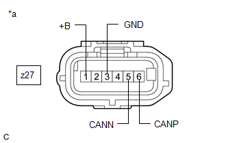
|
*a |
Front view of wire harness connector (to Swing Grille Actuator Assembly) |
Standard Resistance:
|
Terminal No. (Symbol) |
Wiring Color |
Terminal Description |
Condition |
Specified Condition |
|---|---|---|---|---|
|
z27-6(CANP) - z27-5(CANN) |
# |
HIGH-level CAN bus line - LOW-level CAN bus line |
Cable disconnected from negative (-) auxiliary battery terminal |
54 to 69 Ω |
|
z27-6(CANP) - z27-3 (GND) |
# |
HIGH-level CAN bus line - Ground |
Cable disconnected from negative (-) auxiliary battery terminal |
200 Ω or higher |
|
z27-5(CANN) - z27-3 (GND) |
# |
LOW-level CAN bus line - Ground |
Cable disconnected from negative (-) auxiliary battery terminal |
200 Ω or higher |
|
z27-6(CANP) - z27-1 (+B) |
# |
HIGH-level CAN bus line - Auxiliary battery positive (+) |
Cable disconnected from negative (-) auxiliary battery terminal |
6 kΩ or higher |
|
z27-5(CANN) - z27-1 (+B) |
# |
LOW-level CAN bus line - Auxiliary battery positive (+) |
Cable disconnected from negative (-) auxiliary battery terminal |
6 kΩ or higher |
CLEARANCE WARNING ECU ASSEMBLY (w/ Intelligent Clearance Sonar System)
Refer to Terminals of ECU.
Click here
(a) Disconnect the cable from the negative (-) auxiliary battery terminal.
(b) Disconnect the R39 clearance warning ECU assembly connector.
(c) Measure the resistance according to the value(s) in the table below.
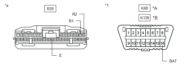
|
*A |
Before Aug. 2018 Production |
*B |
From Aug. 2018 Production |
|
*1 |
DLC3 |
- |
- |
|
*a |
Front view of wire harness connector (to Clearance Warning ECU Assembly) |
- |
- |
Standard Resistance:
Before Aug. 2018 Production:
|
Terminal No. (Symbol) |
Wiring Color |
Terminal Description |
Condition |
Specified Condition |
|---|---|---|---|---|
|
R39-17 (R1) - R39-18 (R2) |
L - W |
HIGH-level CAN bus line - LOW-level CAN bus line |
Cable disconnected from negative (-) auxiliary battery terminal |
54 to 69 Ω |
|
R39-17 (R1) - R39-30 (E) |
L - BR |
HIGH-level CAN bus line - Ground |
Cable disconnected from negative (-) auxiliary battery terminal |
200 Ω or higher |
|
R39-18 (R2) - R39-30 (E) |
W - BR |
LOW-level CAN bus line - Ground |
Cable disconnected from negative (-) auxiliary battery terminal |
200 Ω or higher |
|
R39-17 (R1) - K68-16 (BAT) |
L - R |
HIGH-level CAN bus line - Auxiliary battery positive (+) |
Cable disconnected from negative (-) auxiliary battery terminal |
6 kΩ or higher |
|
R39-18 (R2) - K68-16 (BAT) |
W - R |
LOW-level CAN bus line - Auxiliary battery positive (+) |
Cable disconnected from negative (-) auxiliary battery terminal |
6 kΩ or higher |
From Aug. 2018 Production:
|
Terminal No. (Symbol) |
Wiring Color |
Terminal Description |
Condition |
Specified Condition |
|---|---|---|---|---|
|
R39-17 (R1) - R39-18 (R2) |
L - W |
HIGH-level CAN bus line - LOW-level CAN bus line |
Cable disconnected from negative (-) auxiliary battery terminal |
54 to 69 Ω |
|
R39-17 (R1) - R39-30 (E) |
L - W-B |
HIGH-level CAN bus line - Ground |
Cable disconnected from negative (-) auxiliary battery terminal |
200 Ω or higher |
|
R39-18 (R2) - R39-30 (E) |
W - W-B |
LOW-level CAN bus line - Ground |
Cable disconnected from negative (-) auxiliary battery terminal |
200 Ω or higher |
|
R39-17 (R1) - K138-16 (BAT) |
L - R |
HIGH-level CAN bus line - Auxiliary battery positive (+) |
Cable disconnected from negative (-) auxiliary battery terminal |
6 kΩ or higher |
|
R39-18 (R2) - K138-16 (BAT) |
W - R |
LOW-level CAN bus line - Auxiliary battery positive (+) |
Cable disconnected from negative (-) auxiliary battery terminal |
6 kΩ or higher |
TELEVISION CAMERA CONTROLLER (w/ Panoramic View Monitor System)
Refer to Terminals of ECU.
Click here
(a) Disconnect the cable from the negative (-) auxiliary battery terminal.
(b) Disconnect the R41 television camera controller connector.
(c) Measure the resistance according to the value(s) in the table below.

|
*a |
Front view of wire harness connector (to Television Camera Controller) |
Standard Resistance:
|
Terminal No. (Symbol) |
Wiring Color |
Terminal Description |
Condition |
Specified Condition |
|---|---|---|---|---|
|
R41-12 (CANH) - R41-13 (CANL) |
GR - W |
HIGH-level CAN bus line - LOW-level CAN bus line |
Cable disconnected from negative (-) auxiliary battery terminal |
54 to 69 Ω |
|
R41-12 (CANH) - R41-3 (GND1) |
GR - W-B |
HIGH-level CAN bus line - Ground |
Cable disconnected from negative (-) auxiliary battery terminal |
200 Ω or higher |
|
R41-13 (CANL) - R41-3 (GND1) |
W - W-B |
LOW-level CAN bus line - Ground |
Cable disconnected from negative (-) auxiliary battery terminal |
200 Ω or higher |
|
R41-12 (CANH) - R41-2 (+B) |
GR - R |
HIGH-level CAN bus line - Auxiliary battery positive (+) |
Cable disconnected from negative (-) auxiliary battery terminal |
6 kΩ or higher |
|
R41-13 (CANL) - R41-2 (+B) |
W - R |
LOW-level CAN bus line - Auxiliary battery positive (+) |
Cable disconnected from negative (-) auxiliary battery terminal |
6 kΩ or higher |
|
|
|