- Replacement of fuel injector assembly
- Replacement of fuel pressure sensor (fuel delivery pipe with sensor assembly)
- Replacement of throttle body with motor assembly
- Cleaning the deposits from the throttle body with motor assembly
| Last Modified: 11-20-2023 | 6.11:8.1.0 | Doc ID: RM100000001TBEG |
| Model Year Start: 2021 | Model: Camry | Prod Date Range: [10/2020 - ] |
| Title: 2GR-FKS (INTAKE / EXHAUST): INTAKE MANIFOLD: REMOVAL; 2021 - 2024 MY Camry [10/2020 - ] | ||
REMOVAL
CAUTION / NOTICE / HINT
The necessary procedures (adjustment, calibration, initialization or registration) that must be performed after parts are removed and installed, or replaced during fuel injector assembly removal/installation are shown below.
Necessary Procedures After Parts Removed/Installed/Replaced
|
Replaced Part or Performed Procedure |
Necessary Procedure |
Effect/Inoperative Function when Necessary Procedure not Performed |
Link |
|---|---|---|---|
|
*1: When performing learning using the Techstream.
Click here
|
|||
|
Battery terminal is disconnected/reconnected |
Perform steering sensor zero point calibration |
Lane Tracing Assist System |
|
|
Pre-collision system |
|||
|
Parking Support Brake System*1 |
|||
|
Memorize steering angle neutral point |
Parking assist monitor system |
|
|
|
Panoramic view monitor system |
|
||
|
|
Inspection after repair |
|
|
PROCEDURE
1. PRECAUTION
NOTICE:
After turning the engine switch off, waiting time may be required before disconnecting the cable from the negative (-) battery terminal. Therefore, make sure to read the disconnecting the cable from the negative (-) battery terminal notices before proceeding with work.
Click here
![2020 - 2024 MY Camry [03/2020 - ]; INTRODUCTION: REPAIR INSTRUCTION: PRECAUTION](/t3Portal/stylegraphics/info.gif)
2. DISCHARGE FUEL SYSTEM PRESSURE
Click here
3. DISCONNECT CABLE FROM NEGATIVE BATTERY TERMINAL
NOTICE:
When disconnecting the cable, some systems need to be initialized after the cable is reconnected.
Click here
4. REMOVE COWL TOP VENTILATOR LOUVER SUB-ASSEMBLY
Click here
5. REMOVE FRONT CENTER UPPER SUSPENSION BRACE SUB-ASSEMBLY
Click here
6. REMOVE THROTTLE BODY WITH MOTOR ASSEMBLY
Click here
7. REMOVE V-BANK COVER SUB-ASSEMBLY
Click here
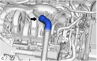
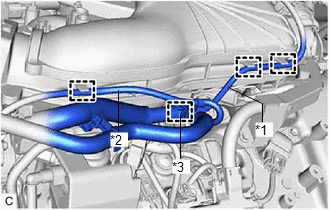
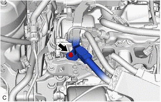
8. DISCONNECT VENTILATION HOSE
|
(a) Slide the clip and disconnect the ventilation hose from the intake air surge tank assembly. |
|
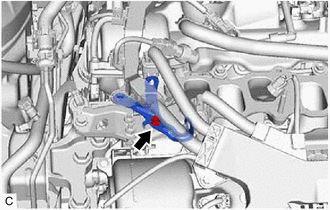
9. DISCONNECT PURGE VALVE (PURGE VSV)
|
(a) Disconnect the No. 1 fuel vapor feed hose from the intake air surge tank assembly. |
|
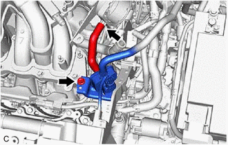
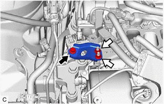
(b) Remove the bolt and disconnect the purge valve (purge VSV) from the intake air surge tank assembly.
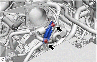
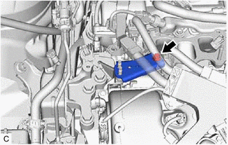
10. REMOVE NO. 2 SURGE TANK STAY
|
(a) Remove the 2 bolts and No. 2 surge tank stay from the intake air surge tank assembly and camshaft housing RH. |
|
11. REMOVE INTAKE AIR SURGE TANK ASSEMBLY
|
(a) Disconnect the vacuum switching valve (for ACIS) connector. |
|
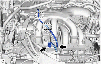
(b) Disengage the 2 clamps to disconnect the vacuum hose sub-assembly from the intake air surge tank assembly.
|
(c) Disengage the 2 clamps to disconnect the vacuum hose sub-assembly from the intake air surge tank assembly. |
|
(d) Disengage the clamp to disconnect the vacuum hose from the intake air surge tank assembly.
(e) Disengage the clamp to disconnect the No. 2 air tube from the intake air surge tank assembly.
(f) Remove the 5 bolts, 2 nuts and intake air surge tank assembly from the intake manifold.
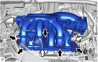

|
Bolt |

|
Nut |
(g) Remove the plug from the intake air surge tank assembly.
12. REMOVE AIR SURGE TANK TO INTAKE MANIFOLD GASKET
|
(a) Remove the air surge tank to intake manifold gasket from the intake air surge tank assembly. |
|
13. REMOVE NO. 1 V-BANK COVER BRACKET
HINT:
Perform this procedure only when replacement of the No. 1 V-bank cover bracket is necessary.
|
(a) Remove the 2 No. 1 V-bank cover brackets from the intake air surge tank assembly. |
|
14. REMOVE NO. 2 ENGINE MOUNTING STAY RH
|
(a) Remove the bolt and disconnect the wire harness clamp from the wire harness clamp bracket. |
|
|
(b) Remove the bolt and separate the wire harness clamp bracket from the No. 2 engine mounting stay RH. |
|
(c) Remove the bolt, 2 nuts and No. 2 engine mounting stay RH from the engine mounting insulator sub-assembly RH.
|
|
Bolt |
|
|
Nut |
|
(d) Remove the bolt and No. 2 engine mounting stay RH from the intake manifold and front No.1 engine mounting bracket LH. |
|
15. DISCONNECT FUEL TUBE SUB-ASSEMBLY
Click here
16. REMOVE FUEL DELIVERY PIPE WITH SENSOR ASSEMBLY
Click here
17. REMOVE NO. 1 DELIVERY PIPE SPACER
Click here
18. REMOVE INJECTOR VIBRATION INSULATOR
Click here
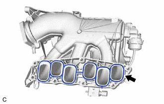
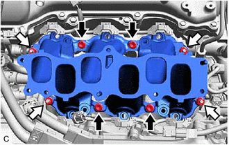
19. REMOVE INTAKE MANIFOLD
(a) Remove the 4 bolts, 4 nuts and intake manifold from the cylinder head sub-assembly.
|
|
Bolt |
|
|
Nut |
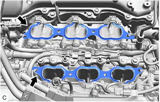
20. REMOVE NO. 1 INTAKE MANIFOLD TO HEAD GASKET
|
(a) Remove the 2 No. 1 intake manifold to head gaskets from each cylinder head sub-assembly. |
|
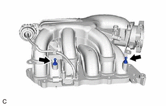
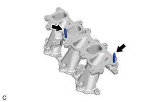
21. REMOVE STUD BOLT
HINT:
If a stud bolt is deformed or the threads are damaged, replace it.
|
(a) Using an E6 "TORX" socket wrench, remove the 2 stud bolts from the intake manifold. |
|
|
|
|