| Last Modified: 11-20-2023 | 6.11:8.1.0 | Doc ID: RM100000001TAMC |
| Model Year Start: 2021 | Model: Camry | Prod Date Range: [10/2020 - ] |
| Title: HEATING / AIR CONDITIONING: COMPRESSOR (for 2GR-FKS): REMOVAL; 2021 - 2024 MY Camry [10/2020 - ] | ||
REMOVAL
CAUTION / NOTICE / HINT
The necessary procedures (adjustment, calibration, initialization, or registration) that must be performed after parts are removed and installed, or replaced during compressor assembly with magnetic clutch removal/installation are shown below.
Necessary Procedure After Parts Removed/Installed/Replaced
|
Replaced Part or Performed Procedure |
Necessary Procedure |
Effect/Inoperative Function when Necessary Procedure not Performed |
Link |
|---|---|---|---|
|
Front bumper assembly (w/ Panoramic view monitor system) |
Front television camera view adjustment |
Panoramic view monitor system |
|
PROCEDURE
1. RECOVER REFRIGERANT FROM REFRIGERATION SYSTEM
Click here
![2018 - 2024 MY Camry [03/2017 - ]; HEATING / AIR CONDITIONING: REFRIGERANT (for HFO-1234yf(R1234yf)): REPLACEMENT+](/t3Portal/stylegraphics/info.gif)
2. REMOVE V-RIBBED BELT
Click here
3. REMOVE RADIATOR ASSEMBLY
Click here
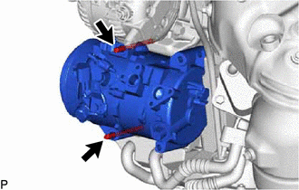
4. DISCONNECT NO. 1 COOLER REFRIGERANT DISCHARGE HOSE SUB-ASSEMBLY
|
(a) Remove the bolt and disconnect the No. 1 cooler refrigerant discharge hose sub-assembly from the compressor assembly with magnetic clutch. |
|
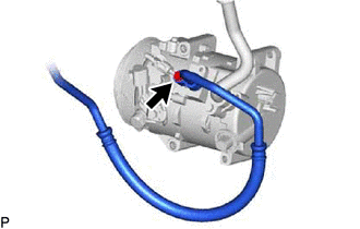
(b) Remove the O-ring from the No. 1 cooler refrigerant discharge hose sub-assembly.
NOTICE:
Seal the openings of the disconnected parts using vinyl tape to prevent moisture and foreign matter from entering them.
5. DISCONNECT SUCTION HOSE SUB-ASSEMBLY
|
(a) Remove the bolt and disconnect the suction hose sub-assembly from the compressor assembly with magnetic clutch. |
|
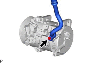
(b) Remove the O-ring from the suction hose sub-assembly.
NOTICE:
Seal the openings of the disconnected parts using vinyl tape to prevent moisture and foreign matter from entering them.
6. REMOVE COMPRESSOR ASSEMBLY WITH MAGNETIC CLUTCH
|
(a) Disconnect each connector. |
|
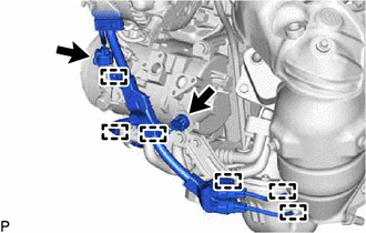
(b) Disengage each clamp.
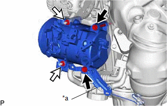
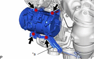
(c) for Type A:
(1) Remove the 2 bolts and 2 nuts, and separate the bracket.
|
*a |
Bracket |

|
Bolt |

|
Nut |
|
(2) Using an E8 "TORX" socket wrench, remove the 2 stud bolts. |
|
(d) for Type B:
|
(1) Remove the 4 bolts and separate the bracket. |
|
(e) Remove the compressor assembly with magnetic clutch.
|
|
|