- Replacement of throttle body with motor assembly
- Cleaning the deposits from the throttle body with motor assembly
- Replacement of engine assembly
- Replacement of cylinder head sub-assembly
- Replacement of camshaft (for intake or exhaust camshaft)
- Replacement of camshaft timing gear assembly
- Replacement of camshaft timing exhaust gear assembly
- Replacement of fuel injector assembly (for port injection)
- Replacement of fuel injector assembly (for direct injection)
- Replacement of fuel pump assembly (for high pressure side)
- Replacement of engine coolant temperature sensor
- Replacement of spark plug
- Replacement of ignition coil assembly
- Air leaks from intake system
- Gas leak from exhaust system is repaired
- Replacement of knock control sensor
| Last Modified: 11-20-2023 | 6.11:8.1.0 | Doc ID: RM100000001T5F1 |
| Model Year Start: 2021 | Model: Camry | Prod Date Range: [10/2020 - 08/2022] |
| Title: 2GR-FKS (ENGINE MECHANICAL): ENGINE UNIT: REMOVAL; 2021 - 2022 MY Camry [10/2020 - 08/2022] | ||
REMOVAL
CAUTION / NOTICE / HINT
The necessary procedures (adjustment, calibration, initialization, or registration) that must be performed after parts are removed and installed, or replaced during engine unit removal/installation are shown below.
Necessary Procedure After Parts Removed/Installed/Replaced
|
Replaced Part or Performed Procedure |
Necessary Procedure |
Effect/Inoperative Function when Necessary Procedure not Performed |
Link |
|---|---|---|---|
| *1: When the ECM is replaced with a new one, reset memory is unnecessary. | |||
|
Battery terminal is disconnected/reconnected |
Perform steering sensor zero point calibration |
Lane Tracing Assist System |
|
|
Pre-collision System |
|||
|
Memorize steering angle neutral point |
Parking Assist Monitor System |
|
|
|
Panoramic view monitor system |
|
||
|
Replacement of ECM |
Vehicle Identification Number (VIN) registration |
MIL comes on |
|
|
ECU communication ID registration (Immobiliser system) |
Engine start function |
|
|
|
|
Inspection After Repair |
|
|
|
Replacement of automatic transaxle assembly |
|
|
|
|
Replacement of ECM (If possible, read the transaxle compensation code from the previous ECM) |
|
||
|
Replacement of ECM (If impossible, read the transaxle compensation code from the previous ECM) |
|
||
|
Replacement of ECM |
Code registration |
|
|
|
Replacement of automatic transaxle fluid |
ATF thermal degradation estimate reset |
The value of the Data List item "ATF Thermal Degradation Estimate" is not estimated correctly. |
|
|
Suspension, tires, etc. (The vehicle height changes because of suspension or tire replacement) |
Rear television camera assembly optical axis (Back camera position setting) |
Parking assist monitor system |
|
|
Replacement of front bumper assembly |
Front television camera view adjustment |
Panoramic view monitor system |
|
|
Suspension, tires, etc. (The vehicle height changes because of suspension or tire replacement) |
|
||
|
Front wheel alignment adjustment |
|
|
|
PROCEDURE
1. REMOVE KNOCK CONTROL SENSOR
Click here
![2021 - 2024 MY Camry [10/2020 - ]; 2GR-FKS (ENGINE CONTROL): KNOCK SENSOR: REMOVAL](/t3Portal/stylegraphics/info.gif)
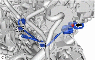
2. REMOVE SENSOR WIRE
|
(a) Disengage the 2 clamps and remove the bolt and sensor wire. |
|
3. REMOVE IGNITION COIL ASSEMBLY
Click here
4. REMOVE VACUUM PUMP ASSEMBLY
Click here
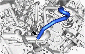
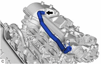
5. REMOVE NO. 3 WATER BY-PASS HOSE
|
(a) Slide the clip and remove the No. 3 water by-pass hose from the water inlet pipe. |
|
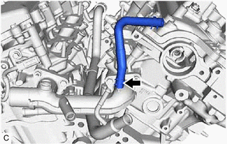
6. REMOVE NO. 2 WATER BY-PASS HOSE
|
(a) Slide the clip and remove the No. 2 water by-pass hose from the water outlet. |
|
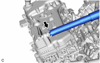
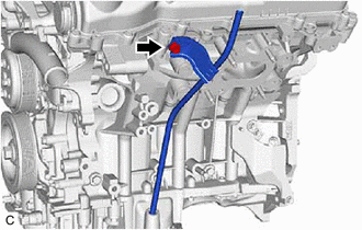
7. REMOVE VENTILATION HOSE
|
(a) Slide the clip and remove the ventilation hose from the PCV valve (ventilation valve sub-assembly). |
|
8. REMOVE NO. 2 VENTILATION HOSE
|
(a) Slide the clip and remove the No. 2 ventilation hose from the cylinder head cover sub-assembly. |
|
9. REMOVE V-RIBBED BELT
Click here
10. REMOVE GENERATOR ASSEMBLY
Click here
11. REMOVE COMPRESSOR ASSEMBLY WITH MAGNETIC CLUTCH
Click here
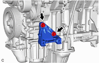
12. REMOVE NO. 1 COMPRESSOR MOUNTING BRACKET
|
(a) Remove the 2 bolts and No. 1 compressor mounting bracket from the cylinder block sub-assembly. |
|
13. REMOVE NO. 2 IDLER PULLEY SUB-ASSEMBLY
Click here
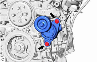
14. REMOVE V-RIBBED BELT TENSIONER ASSEMBLY
|
(a) Remove the 2 bolts and V-ribbed belt tensioner assembly. |
|
15. REMOVE WATER PUMP PULLEY
Click here
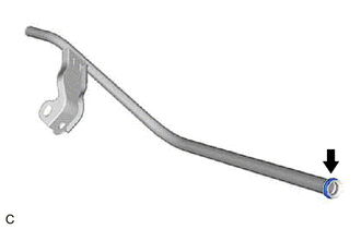
16. REMOVE ENGINE OIL LEVEL DIPSTICK GUIDE
(a) Remove the engine oil level dipstick from the engine oil level dipstick guide.
|
(b) Remove the bolt and engine oil level dipstick guide from the camshaft housing sub-assembly LH and oil pan sub-assembly. |
|
|
(c) Remove the engine oil level dipstick guide O-ring from the engine oil level dipstick guide. |
|
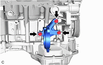
17. REMOVE DRIVE SHAFT BEARING BRACKET
|
(a) Remove the 3 bolts and drive shaft bearing bracket from the cylinder block sub-assembly. |
|
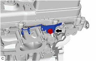
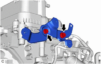
18. REMOVE WIRE HARNESS CLAMP BRACKET
|
(a) Remove the bolt and wire harness clamp bracket from the camshaft housing sub-assembly LH. |
|
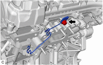
|
(b) Remove the bolt and wire harness clamp bracket from the camshaft housing sub-assembly. |
|
19. REMOVE WATER FILLER BRACKET
|
(a) Remove the 2 bolts and water filler bracket from the camshaft housing sub-assembly LH. |
|
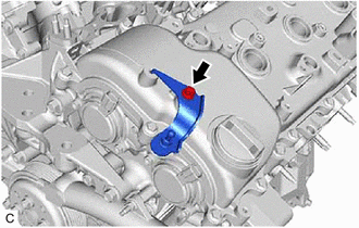
20. REMOVE ENGINE COVER BRACKET
|
(a) Remove the bolt and engine cover bracket from the cylinder head cover sub-assembly LH. |
|
|
|
|