| Last Modified: 09-09-2025 | 6.11:8.1.0 | Doc ID: RM100000001SH5E |
| Model Year Start: 2021 | Model: Camry | Prod Date Range: [10/2020 - ] |
| Title: CRUISE CONTROL: DYNAMIC RADAR CRUISE CONTROL SYSTEM: P057162; Brake Switch "A" Signal Compare Failure; 2021 - 2024 MY Camry [10/2020 - ] | ||
|
DTC |
P057162 |
Brake Switch "A" Signal Compare Failure |
DESCRIPTION
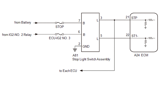
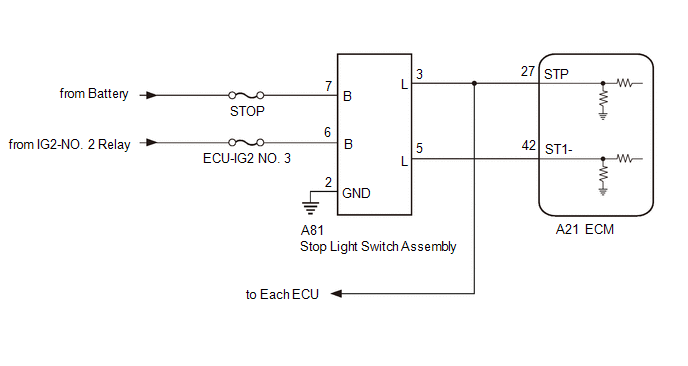
When the brake pedal is depressed, the stop light switch assembly outputs a signal to the ECM. The ECM uses this signal to control cancellation of vehicle speed by the dynamic radar cruise control. When the ECM determines that terminals STP and ST1- of the stop light switch assembly are both less than 1 V, DTC P057162 is stored.
|
DTC No. |
Detection Item |
DTC Detection Condition |
Trouble Area |
DTC Output from |
|---|---|---|---|---|
|
P057162 |
Brake Switch "A" Signal Compare Failure |
When the ignition switch is ON and the dynamic radar cruise control system is operating, the ECM detects that the voltage at terminal STP and ST1- are both less than 1 V for approximately 0.5 seconds or more. |
|
Cruise Control |
WIRING DIAGRAM
for A25A-FKS

for 2GR-FKS

CAUTION / NOTICE / HINT
NOTICE:
PROCEDURE
PROCEDURE
|
1. |
CHECK HARNESS AND CONNECTOR (STOP LIGHT SWITCH ASSEMBLY - BATTERY AND BODY GROUND) |
|
(a) Disconnect the stop light switch assembly connector. |
|
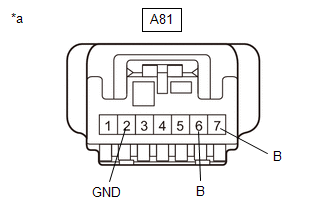
(b) Measure the resistance according to the value(s) in the table below.
Standard Resistance:
|
Tester Connection |
Condition |
Specified Condition |
|---|---|---|
|
A81-2 (GND) - Body ground |
Always |
Below 1 Ω |
(c) Measure the voltage according to the value(s) in the table below.
Standard Voltage:
|
Tester Connection |
Condition |
Specified Condition |
|---|---|---|
|
A81-7 (B) - Body ground |
Always |
11 to 14 V |
|
A81-6 (B) - Body ground |
Ignition switch ON |
11 to 14 V |
|
Ignition switch off |
Below 1 V |
| NG |

|
REPAIR OR REPLACE HARNESS OR CONNECTOR |
|
|
2. |
INSPECT STOP LIGHT SWITCH ASSEMBLY |
| NG |

|
|
|
3. |
CHECK HARNESS AND CONNECTOR (STOP LIGHT SWITCH ASSEMBLY - ECM) |
(a) Disconnect the A81 stop light switch assembly connector.
(b) Disconnect the A24*1 or A21*2 ECM connector.
- *1: for A25A-FKS
- *2: for 2GR-FKS
(c) Disconnect each ECU connector.
(d) Measure the resistance according to the value(s) in the table below.
Standard Resistance:
for A25A-FKS:
|
Tester Connection |
Condition |
Specified Condition |
|---|---|---|
|
A81-3 (L) - A24-21 (STP) |
Always |
Below 1 Ω |
|
A81-5 (L) - A24-22 (ST1-) |
Always |
Below 1 Ω |
|
A81-3 (L) or A24-21 (STP) - Body ground |
Always |
10 kΩ or higher |
|
A81-5 (L) or A24-22 (ST1-) - Body ground |
Always |
10 kΩ or higher |
for 2GR-FKS:
|
Tester Connection |
Condition |
Specified Condition |
|---|---|---|
|
A81-3 (L) - A21-27 (STP) |
Always |
Below 1 Ω |
|
A81-5 (L) - A24-42 (ST1-) |
Always |
Below 1 Ω |
|
A81-3 (L) or A21-27 (STP) - Body ground |
Always |
10 kΩ or higher |
|
A81-5 (L) or A24-42 (ST1-) - Body ground |
Always |
10 kΩ or higher |
| OK |

|
REPLACE ECM |
| NG |

|
REPAIR OR REPLACE HARNESS OR CONNECTOR |
|
|
|
![2020 - 2022 MY Camry [09/2019 - 08/2022]; THEFT DETERRENT / KEYLESS ENTRY: SMART KEY SYSTEM (for Start Function): REGISTRATION](/t3Portal/stylegraphics/info.gif)

