| Last Modified: 11-20-2023 | 6.11:8.1.0 | Doc ID: RM100000001ROZE |
| Model Year Start: 2021 | Model: Camry | Prod Date Range: [10/2020 - 08/2021] |
| Title: LIGHTING (EXT): STOP LIGHT SWITCH: ON-VEHICLE INSPECTION; 2021 MY Camry [10/2020 - 08/2021] | ||
ON-VEHICLE INSPECTION
PROCEDURE
1. INSPECT STOP LIGHT SWITCH ASSEMBLY (for 7 Pin Type)
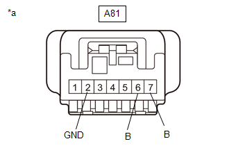
(a) Disconnect the A81 stop light switch assembly connector.
|
(b) Measure the voltage and resistance on the wire harness side connector according to the value(s) in the table below. Standard Voltage:
Standard Resistance:
If the result is not as specified, repair or replace the wire harness or connector. |
|
|
(c) Connect the A81 stop light switch assembly connector. |
|
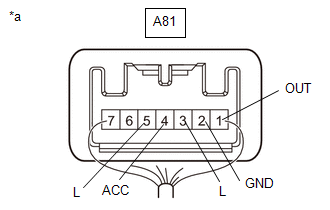
(d) Measure the voltage according to the value(s) in the table below.
Standard Voltage:
|
Tester Connection |
Condition |
Specified Condition |
|---|---|---|
|
A81-1 (OUT) - A81-2 (GND) |
Ignition switch off, brake pedal not depressed |
Below 1 V |
|
A81-1 (OUT) - A81-2 (GND) |
Ignition switch off, brake pedal depressed |
11 to 14 V |
|
A81-3 (L) - A81-2 (GND) |
Ignition switch off, brake pedal not depressed |
Below 1 V |
|
A81-3 (L) - A81-2 (GND) |
Ignition switch off, brake pedal depressed |
11 to 14 V |
|
A81-4 (ACC) - A81-2 (GND) |
Always |
11 to 14 V |
|
A81-5 (L) - A81-2 (GND) |
Ignition switch ON, brake pedal not depressed |
11 to 14 V |
|
A81-5 (L) - A81-2 (GND) |
Ignition switch ON, brake pedal depressed |
Below 1 V |
If the result is not as specified, replace the stop light switch assembly.
2. INSPECT STOP LIGHT SWITCH ASSEMBLY (for 5 Pin Type)
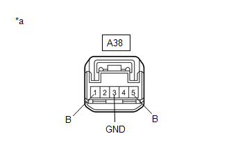
(a) Disconnect the A38 stop light switch assembly connector.
|
(b) Measure the voltage and resistance on the wire harness side connector according to the value(s) in the table below. Standard Voltage:
Standard Resistance:
If the result is not as specified, repair or replace the wire harness or connector. |
|
|
(c) Connect the A38 stop light switch assembly connector. |
|
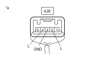
(d) Measure the voltage according to the value(s) in the table below.
Standard Voltage:
|
Tester Connection |
Condition |
Specified Condition |
|---|---|---|
|
A38-2 (L) - A38-3 (GND) |
Brake pedal not depressed |
Below 1 V |
|
A38-2 (L) - A38-3 (GND) |
Brake pedal depressed |
11 to 14 V |
|
A38-4 (L) - A38-3 (GND) |
Ignition switch ON, brake pedal not depressed |
11 to 14 V |
|
A38-4 (L) - A38-3 (GND) |
Ignition switch ON, brake pedal depressed |
Below 1 V |
If the result is not as specified, replace the stop light switch assembly.
|
|
|