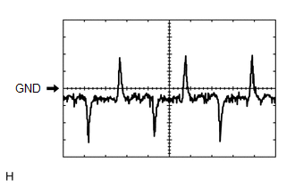
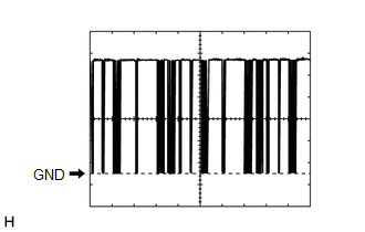
- Engine running
- Blower switch: LO
- A/C switch: Off
| Last Modified: 11-20-2023 | 6.11:8.1.0 | Doc ID: RM100000001E5Z8 |
| Model Year Start: 2019 | Model: Camry | Prod Date Range: [08/2018 - 10/2020] |
| Title: HEATING / AIR CONDITIONING: AIR CONDITIONING SYSTEM (for Automatic Air Conditioning System): TERMINALS OF ECU; 2019 - 2020 MY Camry [08/2018 - 10/2020] | ||
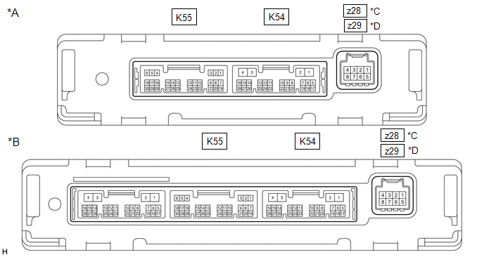
TERMINALS OF ECU
CHECK AIR CONDITIONING AMPLIFIER ASSEMBLY
|
*A |
w/o Seat Heater |
*B |
w/ Seat Heater |
|
*C |
for Dual Type |
*D |
for Single Type |
HINT:
- Check from the rear of the connector while it is connected to the air conditioning amplifier assembly.
- Make sure to wait at least 2 minutes after turning the ignition switch off before performing an ECU terminal inspection.
|
Terminal No. (Symbol) |
Wiring Color |
Terminal Description |
Condition |
Specified Condition |
|---|---|---|---|---|
|
K55-1 (SG-1) - Body ground |
LG - Body ground |
Ground for cooler (room temp. sensor) thermistor |
Always |
Below 1 V |
|
K55-2 (SG-2) - Body ground |
W - Body ground |
Ground for thermistor assembly |
Always |
Below 1 V |
|
K55-3 (SG-4) - Body ground |
L - Body ground |
Ground for air conditioner pressure sensor |
Always |
Below 1 V |
|
K55-6 (S5-3) - K55-3 (SG-4) |
GR - L |
Power supply for air conditioner pressure sensor |
Ignition switch ON |
4.75 to 5.25 V |
|
Ignition switch off |
Below 1 V |
|||
|
K55-9 (MGC) - K54-9 (GND)*3 |
G - W-B |
Magnetic clutch operation signal |
|
11 to 14 V |
|
Below 1 V |
|||
|
K55-13 (TAM) - K55-2 (SG-2) |
R - W |
Thermistor assembly signal |
|
1.05 to 1.45 V |
|
0.64 to 0.87 V |
|||
|
K55-14 (TR) - K55-1 (SG-1) |
GR - LG |
Cooler (room temp. sensor) thermistor signal |
|
1.05 to 1.45 V |
|
0.64 to 0.87 V |
|||
|
K55-20 (ECOS) - K54-9 (GND)*4 |
W - W-B |
ECO switch assembly (electric parking brake switch assembly) signal |
|
11 to 14 V |
|
Below 1 V |
|||
|
K55-21 (LOCK) - K55-2 (SG-2)*3 |
B - W |
A/C lock sensor signal |
|
Pulse generation (See waveform 1) |
|
K55-24 (PRE) - K55-3 (SG-4) |
W - L |
Air conditioner pressure sensor signal |
|
4.61 V or higher |
|
Below 0.74 V |
|||
|
0.74 to 4.61 V |
|||
|
K54-1 (B) - K54-4 (GND) |
LA-B - W-B |
Power source (Back-up) |
Always |
11 to 14 V |
|
K54-2 (IG+) - K54-4 (GND) |
LA-GR - W-B |
Power source (IG) |
Ignition switch ON |
11 to 14 V |
|
Ignition switch off |
Below 1 V |
|||
|
K54-3 (SOL+) - K54-4 (GND) |
R - W-B |
Compressor solenoid operation signal |
|
Pulse generation (See waveform 2) |
|
K54-4 (GND) - Body ground |
W-B - Body ground |
Ground for main power supply |
Always |
Below 1 V |
|
K54-6 (BLW) - K54-4 (GND) |
LG - W-B |
Blower motor speed control signal |
|
Pulse generation (See waveform 3) |
|
K54-11 (CANH) - K54-12 (CANL) |
SB - W |
CAN communication system |
CAN communication is performed |
Pulse generation |
|
K54-14 (LIN1) - K54-4 (GND) |
LG - W-B*6,*7,*10 |
LIN communication signal |
Ignition switch ON |
Pulse generation (See waveform 4) |
|
BE - W-B*5,*7 or *7,*9 |
LIN communication signal |
Ignition switch ON |
Pulse generation (See waveform 4) |
|
|
B - W-B*5,*8 |
LIN communication signal |
Ignition switch ON |
Pulse generation (See waveform 4) |
|
|
z28-2 (BUS G) - Body ground*1 |
- |
Ground for BUS IC |
Always |
Below 1 V |
|
z28-3 (BUS) - z28-2 (BUS G)*1 |
- |
BUS IC control signal |
Ignition switch ON |
Pulse generation (See waveform 5) |
|
z28-4 (B BUS) - z28-2 (BUS G)*1 |
- |
Power supply for BUS IC |
Ignition switch off |
11 to 14 V |
|
z28-5 (SG) - Body ground*1 |
GR - Body ground |
Ground for No. 1 cooler thermistor |
Always |
Below 1 V |
|
z28-6 (TE) - z28-5 (SG)*1 |
GR - GR |
No. 1 cooler thermistor signal |
|
1.7 to 2.1 V |
|
0.9 to 1.3 V |
|||
|
z29-2 (1A) - Body ground*2 |
- |
Ground for BUS IC |
Always |
Below 1 V |
|
z29-3 (2A) - z29-2 (1A)*2 |
- |
BUS IC control signal |
Ignition switch ON |
Pulse generation (See waveform 5) |
|
z29-4 (3A) - z29-2 (1A)*2 |
- |
Power supply for BUS IC |
Ignition switch off |
11 to 14 V |
|
z29-5 (4A) - Body ground*2 |
GR - Body ground |
Ground for No. 1 cooler thermistor |
Always |
Below 1 V |
|
z29-6 (5A) - z29-5 (4A)*2 |
GR - GR |
No. 1 cooler thermistor signal |
|
1.7 to 2.1 V |
|
0.9 to 1.3 V |
- *1: for Dual Type
- *2: for Single Type
- *3: for 2GR-FKS
- *4: w/ Electric Parking Brake System
- *5: w/ Seat Heater
- *6: w/o Seat Heater
- *7: for 7 Inch Display
- *8: for 8 Inch Display
- *9: for TMC Made
- *10: for TMMK Made
(a) Waveform 1:
|
Item |
Content |
|---|---|
|
Terminal No. |
K55-21 (LOCK) - K55-2 (SG-2) |
|
Tool Setting |
200 mV/DIV., 10 ms./DIV. |
|
Condition |
|
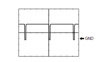
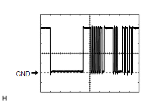
(b) Waveform 2:
|
Item |
Content |
|---|---|
|
Terminal No. |
K54-3 (SOL+) - K54-4 (GND) |
|
Tool Setting |
5 V/DIV., 500 μs./DIV. |
|
Condition |
|
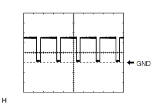
(c) Waveform 3:
|
Item |
Content |
|---|---|
|
Terminal No. |
K54-6 (BLW) - K54-4 (GND) |
|
Tool Setting |
2 V/DIV., 1 ms./DIV. |
|
Condition |
|
(d) Waveform 4:
|
Item |
Content |
|---|---|
|
Terminal No. |
K54-14 (LIN1) - K54-4 (GND) |
|
Tool Setting |
2 V/DIV., 20 ms./DIV. |
|
Condition |
Ignition switch ON |
(e) Waveform 5:
|
Item |
Content |
|---|---|
|
Terminal No. |
z28-3 (BUS) - z28-2 (BUS G)*1 z29-3 (2A) - z29-2 (1A)*2 |
|
Tool Setting |
2 V/DIV., 2 ms./DIV. |
|
Condition |
Ignition switch ON |
- *1: for Dual Type
- *2: for Single Type
CHECK AIR CONDITIONING CONTROL PANEL (RADIO AND DISPLAY RECEIVER ASSEMBLY) (for 8 Inch Display)

HINT:
Check from the rear of the connector while it is connected to the air conditioning control panel (radio and display receiver assembly).
|
Terminal No. (Symbol) |
Wiring Color |
Terminal Description |
Condition |
Specified Condition |
|---|---|---|---|---|
|
h1-2 (IG1) - h1-6 (GND) |
SB - W-B |
Power source (IG) |
Ignition switch off |
Below 1 V |
|
Ignition switch ON |
11 to 14 V |
|||
|
h1-3 (+B) - h1-6 (GND) |
G - W-B |
Power source (Back-up) |
Ignition switch off |
11 to 14 V |
|
h1-6 (GND) - Body ground |
W-B - Body ground |
Ground for air conditioning control panel (radio and display receiver assembly) |
Always |
Below 1 V |
|
h1-10 (ACC) - h1-6 (GND) |
R - W-B |
Power source (ACC) |
Ignition switch off |
Below 1 V |
|
Ignition switch ACC |
11 to 14 V |
|||
|
h1-11 (ILL+) - Body ground |
W - Body ground |
Illumination signal |
Light control switch in off position |
Below 1 V |
|
Light control switch in tail or head position |
11 to 14 V |
|||
|
h1-15 (ILL-) - Body ground |
L - Body ground |
Illumination signal |
Always |
Below 1 V |
CHECK AIR CONDITIONING CONTROL ASSEMBLY (for 7 Inch Display)

HINT:
Check from the rear of the connector while it is connected to the air conditioning control assembly.
|
Terminal No. (Symbol) |
Wiring Color |
Terminal Description |
Condition |
Specified Condition |
|---|---|---|---|---|
|
K26-2 (IG+) - K26-6 (GND) |
GR - W-B |
Power source (IG) |
Ignition switch off |
Below 1 V |
|
Ignition switch ON |
11 to 14 V |
|||
|
K26-6 (GND) - Body ground |
W-B - Body ground |
Ground for air conditioning control assembly |
Always |
Below 1 V |
|
K26-9 (LIN1) - Body ground |
LG - Body ground |
LIN communication signal |
Ignition switch ON |
Pulse generation (See waveform) |
|
K26-11 (ILL+) - Body ground |
W - Body ground |
Illumination signal |
Light control switch in off position |
Below 1 V |
|
Light control switch in tail or head position |
11 to 14 V |
|||
|
K26-15 (ILL-) - Body ground |
B - Body ground |
Illumination signal |
Always |
Below 1 V |
(a) Waveform:
|
Item |
Content |
|---|---|
|
Terminal No. |
K26-9 (LIN1) - Body ground |
|
Tool Setting |
2 V/DIV., 20 ms./DIV. |
|
Condition |
Ignition switch ON |
|
|
|