- Between A30-3 (CA2H) and A30-1 (SGND)
- Between A30-5 (CA1P) and A30-1 (SGND)
| Last Modified: 11-20-2023 | 6.11:8.1.0 | Doc ID: RM100000001DYOF |
| Model Year Start: 2019 | Model: Camry | Prod Date Range: [08/2018 - 10/2020] |
| Title: CRUISE CONTROL: DYNAMIC RADAR CRUISE CONTROL SYSTEM: TERMINALS OF ECU; 2019 - 2020 MY Camry [08/2018 - 10/2020] | ||
TERMINALS OF ECU
CHECK ECM (for A25A-FKS)
HINT:
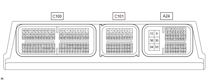
The standard voltage, resistance and waveform between each pair of the ECM terminals is shown in the table below. The appropriate conditions for checking each pair of the terminals is also indicated. The result of checks should be compared with the standard voltage, resistance and waveform for each pair of the terminals as displayed in the Specified Condition column. The illustration above can be used as a reference to identify the ECM terminal locations.
|
Terminal No. (Symbols) |
Wiring Color |
Terminal Description |
Condition |
Specified Condition |
|---|---|---|---|---|
|
A24-1 (BATT) - A24-10 (E1) |
G - W-B |
Battery (for measuring battery voltage and for ECM memory) |
Always |
11 to 14 V |
|
C101-23 (D) - A24-10 (E1) |
R - W-B |
D shift position signal |
Ignition switch ON, shift lever in D |
11 to 14 V |
|
Ignition switch ON, shift lever not in D |
Below 1 V |
|||
|
A24-14 (S) - A24-10 (E1) |
GR - W-B |
S shift position signal |
Ignition switch ON, shift lever in S |
11 to 14 V |
|
Ignition switch ON, shift lever not in S |
Below 1 V |
|||
|
A24-21 (STP) - A24-10 (E1) |
SB - W-B |
Stop light switch assembly signal |
Brake pedal depressed |
11 to 14 V |
|
Brake pedal released |
Below 1 V |
|||
|
A24-27 (CCS) - A24-28 (ECCS) |
R - BE |
Steering pad switch circuit |
Cruise control switch not pushed |
1 MΩ or higher |
|
Cruise control main switch pushed |
Below 2.5 Ω |
|||
|
+RES switch pushed |
235 to 245 Ω |
|||
|
-SET switch pushed |
617 to 643 Ω |
|||
|
CANCEL switch pushed |
1509 to 1571 Ω |
|||
|
A24-22 (ST1-) - A24-10 (E1) |
LG - W-B |
Stop light switch assembly signal |
Ignition switch ON, brake pedal depressed |
Below 1 V |
|
Ignition switch ON, brake pedal released |
11 to 14 V |
|||
|
A24-19 (SFTD) - A24-10 (E1) |
W - W-B |
Down-shift position switch signal |
Ignition switch ON, shift lever in S |
11 to 14 V |
|
Ignition switch ON, shift lever in "-" |
Below 1 V |
|||
|
A24-20 (SFTU) - A24-10 (E1) |
G - W-B |
Up-shift position switch signal |
Ignition switch ON, shift lever in S |
11 to 14 V |
|
Ignition switch ON, shift lever in "+" |
Below 1 V |
CHECK ECM (for 2GR-FKS)
HINT:
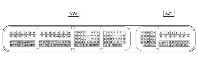
The standard voltage, resistance and waveform between each pair of the ECM terminals is shown in the table below. The appropriate conditions for checking each pair of the terminals is also indicated. The result of checks should be compared with the standard voltage, resistance and waveform for each pair of the terminals as displayed in the Specified Condition column. The illustration above can be used as a reference to identify the ECM terminal locations.
|
Terminal No. (Symbols) |
Wiring Color |
Terminal Description |
Condition |
Specified Condition |
|---|---|---|---|---|
|
A21-1 (BATT) - A96-53 (E1) |
R - W-B |
Battery (for measuring battery voltage and for ECM memory) |
Always |
11 to 14 V |
|
C96-139 (D) - A96-53 (E1) |
R - W-B |
D shift position signal |
Ignition switch ON, shift lever in D |
11 to 14 V |
|
Ignition switch ON, shift lever not in D |
Below 1 V |
|||
|
A21-17 (S) - A96-53 (E1) |
GR - W-B |
S shift position signal |
Ignition switch ON, shift lever in S |
11 to 14 V |
|
Ignition switch ON, shift lever not in S |
Below 1 V |
|||
|
A21-27 (STP) - A96-53 (E1) |
SB - W-B |
Stop light switch assembly signal |
Brake pedal depressed |
11 to 14 V |
|
Brake pedal released |
Below 1 V |
|||
|
A21-41 (CCS) - A96-53 (E1) |
R - W-B |
Steering pad switch circuit |
Cruise control switch not pushed |
1 MΩ or higher |
|
Cruise control main switch pushed |
Below 2.5 Ω |
|||
|
+RES switch pushed |
235 to 245 Ω |
|||
|
-SET switch pushed |
617 to 643 Ω |
|||
|
CANCEL switch pushed |
1509 to 1571 Ω |
|||
|
A21-42 (ST1-) - A96-53 (E1) |
LG - W-B |
Stop light switch assembly signal |
Ignition switch ON, brake pedal depressed |
Below 1 V |
|
Ignition switch ON, brake pedal released |
11 to 14 V |
|||
|
A21-37 (SFTD) - A96-53 (E1) |
W - W-B |
Down-shift position switch signal |
Ignition switch ON, shift lever in S |
11 to 14 V |
|
Ignition switch ON, shift lever in "-" |
Below 1 V |
|||
|
A21-38 (SFTU) - A96-53 (E1) |
G - W-B |
Up-shift position switch signal |
Ignition switch ON, shift lever in S |
11 to 14 V |
|
Ignition switch ON, shift lever in "+" |
Below 1 V |

|
Terminal No. (Symbol) |
Wiring Color |
Terminal Description |
Condition |
Specified Condition |
|---|---|---|---|---|
|
A30-1 (SGND) - Body ground |
W-B - Body ground |
Ground |
Always |
Below 1 Ω |
|
A30-2 (CA2L) - A30-1 (SGND) |
W - W-B |
CAN communication signal |
Ignition switch ON |
Pulse generation (See waveform 2) |
|
A30-3 (CA2H) - A30-1 (SGND) |
R - W-B |
CAN communication signal |
Ignition switch ON |
Pulse generation (See waveform 1) |
|
A30-5 (CA1P) - A30-1 (SGND) |
G - W-B |
CAN communication signal |
Ignition switch ON |
Pulse generation (See waveform 1) |
|
A30-6 (CA1N) - A30-1 (SGND) |
W - W-B |
CAN communication signal |
Ignition switch ON |
Pulse generation (See waveform 2) |
|
A30-8 (IGB) - A30-1 (SGND) |
B - W-B |
Power source |
Ignition switch ON |
11 to 14 V |
CHECK MILLIMETER WAVE RADAR SENSOR ASSEMBLY
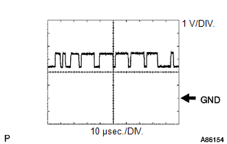
(a) Waveform 1
(1) CAN communication signal
|
Item |
Content |
|---|---|
|
Tester Connection |
|
|
Tool Setting |
1 V/DIV., 10 μsec./DIV. |
|
Condition |
Ignition switch ON |
HINT:
The waveform varies depending on the CAN communication signal.
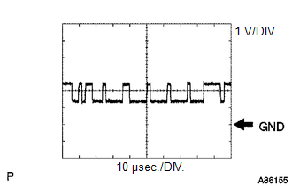
(b) Waveform 2
(1) CAN communication signal
|
Item |
Content |
|---|---|
|
Tester Connection |
|
|
Tool Setting |
1 V/DIV., 10 μsec./DIV. |
|
Condition |
Ignition switch ON |
HINT:
The waveform varies depending on the CAN communication signal.
NOTICE:
- DTCs may be output when connectors are disconnected during inspection. Therefore, be sure to clear the DTCs using the Techstream once the inspection has been completed.
- Do not apply excessive force to the V6 forward recognition camera connector.

CHECK FORWARD RECOGNITION CAMERA
|
Terminal No. (Symbol) |
Wiring Color |
Terminal Description |
Condition |
Specified Condition |
|---|---|---|---|---|
|
V6-7 (IGB) - V6-10 (GND) |
LA-P - W-B |
Power source |
Ignition switch ON |
11 to 14 V |
|
Ignition switch off |
Below 1 V |
|||
|
V6-5 (CA1P) - V6-10 (GND) |
L - W-B |
CAN communication signal |
Ignition switch ON |
Pulse generation (See waveform 1) |
|
V6-11 (CA1N) - V6-10 (GND) |
W - W-B |
CAN communication signal |
Ignition switch ON |
Pulse generation (See waveform 2) |
|
V6-6 (CANH) - V6-10 (GND) |
G - W-B |
CAN communication signal |
Ignition switch ON |
Pulse generation (See waveform 1) |
|
V6-12 (CANL) - V6-10 (GND) |
W - W-B |
CAN communication signal |
Ignition switch ON |
Pulse generation (See waveform 2) |
|
V6-3 (LKSW) - V6-10 (GND) |
V - W-B |
Vehicle-to-vehicle distance control switch signal |
Ignition switch ON, vehicle-to-vehicle distance control switch not pushed |
4.75 to 5.25 V |
|
Ignition switch ON, vehicle-to-vehicle distance control switch pushed |
Below 1 V |
|||
|
V6-10 (GND) - Body ground |
W-B - Body ground |
Ground |
Always |
Below 1 Ω |
(a) Waveform 1
(1) CAN communication signal
|
Item |
Content |
|---|---|
|
Tester Connection |
|
|
Tool Setting |
1 V/DIV., 10 μsec./DIV. |
|
Condition |
Ignition switch ON |
HINT:
The waveform varies depending on the CAN communication signal.
(b) Waveform 2
(1) CAN communication signal
|
Item |
Content |
|---|---|
|
Tester Connection |
|
|
Tool Setting |
1 V/DIV., 10 μsec./DIV. |
|
Condition |
Ignition switch ON |
HINT:
The waveform varies depending on the CAN communication signal.
|
|
|