- DTC judgment completed
- System normal
| Last Modified: 09-09-2025 | 6.11:8.1.0 | Doc ID: RM100000001DVQJ |
| Model Year Start: 2019 | Model: Camry | Prod Date Range: [08/2018 - 03/2020] |
| Title: A25A-FKS (ENGINE CONTROL): SFI SYSTEM: P046012,P046014; Fuel Level Sensor "A" Circuit Short to Battery; 2019 - 2020 MY Camry [08/2018 - 03/2020] | ||
|
DTC |
P046012 |
Fuel Level Sensor "A" Circuit Short to Battery |
|
DTC |
P046014 |
Fuel Level Sensor "A" Circuit Short to Ground or Open |
DESCRIPTION
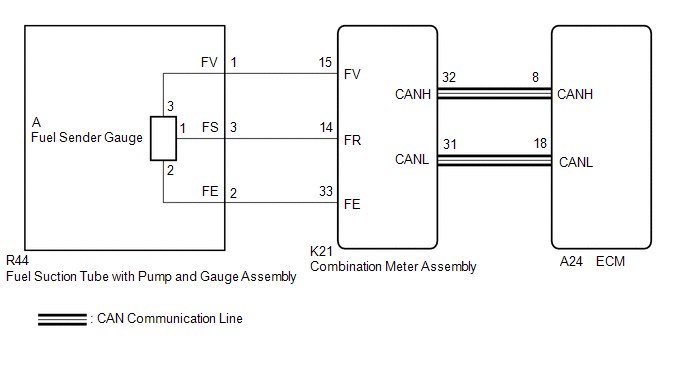
The fuel sender gauge is located inside the fuel tank and measures the amount of fuel. The fuel sender gauge converts the fuel level in the fuel tank into a voltage value and outputs it to the combination meter assembly. The ECM determines when it is necessary to refuel the vehicle based on changes in the output value of the fuel sender gauge.
|
DTC No. |
Detection Item |
DTC Detection Condition |
Trouble Area |
MIL |
Memory |
Note |
|---|---|---|---|---|---|---|
|
P046012 |
Fuel Level Sensor "A" Circuit Short to Battery |
Fuel sender gauge output voltage is higher than 4.73 V for 30 seconds or more (2 trip detection logic). |
|
Comes on |
DTC stored |
|
|
P046014 |
Fuel Level Sensor "A" Circuit Short to Ground or Open |
Fuel sender gauge output voltage is less than 0.25 V for 30 seconds or more (2 trip detection logic). |
|
Comes on |
DTC stored |
|
MONITOR DESCRIPTION
The combination meter assembly sends fuel level sensor signals to the ECM via CAN communication. When the ignition switch is ON, if the output voltage of the fuel level sensor is less than 0.25 V or higher than 4.73 V for 30 seconds or more, the ECM will illuminate the MIL and store this DTC.
MONITOR STRATEGY
|
Related DTCs |
P0462: Fuel level sensor range check (low voltage) P0463: Fuel level sensor range check (high voltage) |
|
Required Sensors/Components (Main) |
Fuel level sensor |
|
Required Sensors/Components (Related) |
- |
|
Frequency of Operation |
Continuous |
|
Duration |
30 seconds |
|
MIL Operation |
2 driving cycles |
|
Sequence of Operation |
None |
TYPICAL ENABLING CONDITIONS
|
All of the following conditions are met |
- |
|
Battery voltage |
8 V or higher |
|
Ignition switch |
ON |
|
Lost communication with instrument panel cluster control module (U0155) |
Not detected |
TYPICAL MALFUNCTION THRESHOLDS
P0462
|
Fuel level sensor voltage |
Less than 0.25 V |
P0463
|
Fuel level sensor voltage |
Higher than 4.73 V |
CONFIRMATION DRIVING PATTERN
HINT:
-
After repair has been completed, clear the DTC and then check that the vehicle has returned to normal by performing the following All Readiness check procedure.
Click here
![2018 - 2024 MY Camry [03/2017 - ]; A25A-FKS (ENGINE CONTROL): SFI SYSTEM: DTC CHECK / CLEAR](/t3Portal/stylegraphics/info.gif)
-
When clearing the permanent DTCs, refer to the "CLEAR PERMANENT DTC" procedure.
Click here
- Connect the Techstream to the DLC3.
- Turn the ignition switch to ON.
- Turn the Techstream on.
- Clear the DTCs (even if no DTCs are stored, perform the clear DTC procedure).
- Turn the ignition switch off and wait for at least 30 seconds.
- Turn the ignition switch to ON [A].
- Turn the Techstream on.
- Wait 30 seconds or more [B].
- Enter the following menus: Powertrain / Engine / Trouble Codes [C].
-
Read the pending DTCs.
HINT:
- If a pending DTC is output, the system is malfunctioning.
- If a pending DTC is not output, perform the following procedure.
- Enter the following menus: Powertrain / Engine / Utility / All Readiness.
- Input the DTC: P046012 or P046014.
-
Check the DTC judgment result.
Techstream Display
Description
NORMAL
ABNORMAL
- DTC judgment completed
- System abnormal
INCOMPLETE
- DTC judgment not completed
- Perform driving pattern after confirming DTC enabling conditions
HINT:
- If the judgment result shows NORMAL, the system is normal.
- If the judgment result shows ABNORMAL, the system has a malfunction.
-
[A] to [C]: Normal judgment procedure.
The normal judgment procedure is used to complete DTC judgment and also used when clearing permanent DTCs.
- When clearing the permanent DTCs, do not disconnect the cable from the battery terminal or attempt to clear the DTCs during this procedure, as doing so will clear the universal trip and normal judgment histories.
WIRING DIAGRAM
CAUTION / NOTICE / HINT
HINT:
Read freeze frame data using the Techstream. The ECM records vehicle and driving condition information as freeze frame data the moment a DTC is stored. When troubleshooting, freeze frame data can help determine if the vehicle was moving or stationary, if the engine was warmed up or not, if the air fuel ratio was lean or rich, and other data from the time the malfunction occurred.
PROCEDURE
PROCEDURE
|
1. |
CHECK HARNESS AND CONNECTOR (FUEL SUCTION TUBE WITH PUMP AND GAUGE ASSEMBLY - COMBINATION METER ASSEMBLY) |
(a) Disconnect the fuel suction tube with pump and gauge assembly connector.
(b) Disconnect the combination meter assembly connector.
(c) Measure the resistance according to the value(s) in the table below.
Standard Resistance:
|
Tester Connection |
Condition |
Specified Condition |
|---|---|---|
|
R44-1 (FV) - K21-15 (FV) |
Always |
Below 1 Ω |
|
R44-3 (FS) - K21-14 (FR) |
Always |
Below 1 Ω |
|
R44-2 (FE) - K21-33 (FE) |
Always |
Below 1 Ω |
|
R44-1 (FV) or K21-15 (FV) - Body ground and other terminals |
Always |
10 kΩ or higher |
|
R44-3 (FS) or K21-14 (FR) - Body ground and other terminals |
Always |
10 kΩ or higher |
| NG |

|
REPAIR OR REPLACE HARNESS OR CONNECTOR |
|

|
2. |
INSPECT FUEL SENDER GAUGE ASSEMBLY |
(a) Remove the fuel sender gauge assembly.
Click here
(b) Inspect the fuel sender gauge assembly.
Click here
| NG |
|
|
|
3. |
INSPECT FUEL SUCTION TUBE WITH PUMP AND GAUGE ASSEMBLY |
|
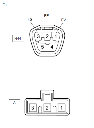
*a |
Component without harness connected (Fuel Suction Tube with Pump and Gauge Assembly) |
(a) Measure the resistance according to the value(s) in the table below.
Standard Resistance:
|
Tester Connection |
Condition |
Specified Condition |
|---|---|---|
|
R44-1 (FV) - A-3 |
Always |
Below 1 Ω |
|
R44-2 (FE) - A-2 |
Always |
Below 1 Ω |
|
R44-3 (FS) - A-1 |
Always |
Below 1 Ω |
|
R44-1 (FV) - R44-3 (FS) or A-3 - A-1 |
Always |
10 kΩ or higher |
|
R44-1 (FV) - R44-2 (FE) or A-3 - A-2 |
Always |
10 kΩ or higher |
|
R44-2 (FE) - R44-3 (FS) or A-2 - A-1 |
Always |
10 kΩ or higher |
| OK |
|
| NG |
|
REPLACE FUEL SUCTION TUBE WITH PUMP AND GAUGE ASSEMBLY Click here
|
|
|
|