- Replacement of fuel injector assembly (for Port Injection)
- Replacement of fuel injector assembly (for Direct Injection)
- Replacement of throttle body with motor assembly
- Cleaning the deposits from the throttle body with motor assembly
| Last Modified: 11-20-2023 | 6.11:8.1.0 | Doc ID: RM1000000015IJI |
| Model Year Start: 2018 | Model: Camry | Prod Date Range: [06/2017 - 10/2020] |
| Title: 2GR-FKS (FUEL): FUEL INJECTOR (for Direct Injection): REMOVAL; 2018 - 2020 MY Camry [06/2017 - 10/2020] | ||
REMOVAL
CAUTION / NOTICE / HINT
The necessary procedures (adjustment, calibration, initialization or registration) that must be performed after parts are removed and installed, or replaced during fuel injector assembly removal/installation are shown below.
Necessary Procedures After Parts Removed/Installed/Replaced
|
Replaced Part or Performed Procedure |
Necessary Procedure |
Effect/Inoperative Function when Necessary Procedure not Performed |
Link |
|---|---|---|---|
|
*: When performing learning using the Techstream.
Click here
|
|||
|
Battery terminal is disconnected/reconnected |
Perform steering sensor zero point calibration |
Lane departure alert system (w/ Steering Control) |
|
|
Pre-collision system |
|||
|
Intelligent clearance sonar system* |
|||
|
Memorize steering angle neutral point |
Parking assist monitor system |
|
|
|
Panoramic view monitor system |
|
||
|
|
Inspection after repair |
|
|
CAUTION:
-
Never perform work on fuel system components near any possible ignition sources.
- Vaporized fuel could ignite, resulting in a serious accident.
-
Do not perform work on fuel system components without first disconnecting the cable from the negative (-) battery terminal.
- Sparks could cause vaporized fuel to ignite, resulting in a serious accident.
-
To prevent serious injury due to fuel spray from the high-pressure fuel lines, always discharge fuel system pressure before removing any fuel system components.
PROCEDURE
1. REMOVE FUEL (ENGINE ROOM SIDE) PUMP ASSEMBLY (for High Pressure)
Click here
![2018 - 2020 MY Camry [06/2017 - 10/2020]; 2GR-FKS (FUEL): FUEL PUMP (for High Pressure): REMOVAL](/t3Portal/stylegraphics/info.gif)
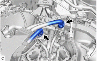
2. REMOVE NO. 2 FUEL PIPE SUB-ASSEMBLY
CAUTION:
To prevent serious injury due to fuel spray from the high-pressure fuel lines, always discharge fuel system pressure before removing any fuel system components.
|
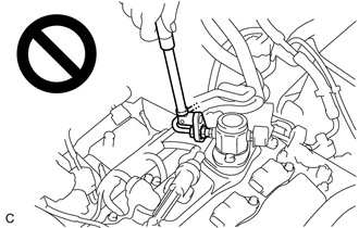
(a) Using a 17 mm union nut wrench, loosen the 2 union nuts of the No. 2 fuel pipe sub-assembly. |
|
(b) Remove the No. 2 fuel pipe sub-assembly from the fuel delivery pipe with sensor assembly LH and fuel delivery pipe RH.
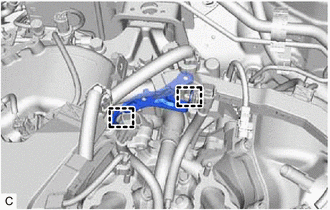
3. REMOVE WIRE HARNESS CLAMP BRACKET
|
(a) Disconnect the No. 6 engine wire connector and No. 7 engine wire connector. |
|
|
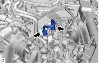
(b) Disengage the 2 clamps to remove the wire harness clamp bracket. |
|
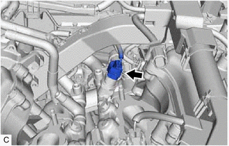
4. REMOVE FUEL DELIVERY PIPE WITH SENSOR ASSEMBLY LH
|
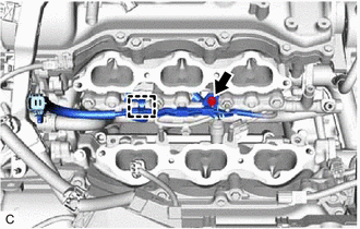
(a) Disconnect the fuel pressure sensor connector. |
|
|
(b) Remove the bolt. |
|
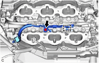
(c) Disengage the clamp to disconnect the No. 7 engine wire from the fuel delivery pipe with sensor assembly LH.
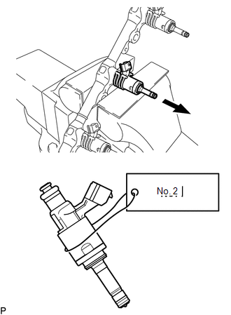
(d) Remove the 2 bolts, 2 nuts and fuel delivery pipe with sensor assembly LH with the 3 fuel injector assemblies from the cylinder head LH.
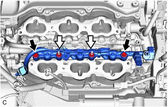

|
Bolt |

|
Nut |
NOTICE:
- If fuel intrudes into the combustion chamber, there may be adverse affects to the engine main body.
- Make sure not to touch or strike the tips of the fuel injector assemblies.
- Pull and remove the fuel delivery pipe with sensor assembly LH in a straight line without tilting it.
|
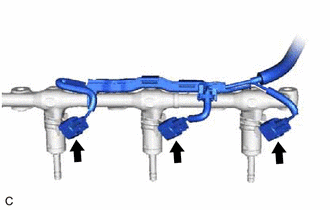
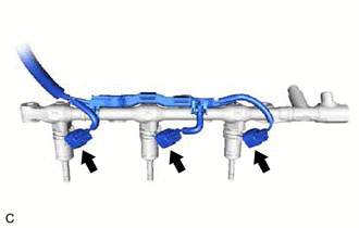
(e) Disconnect the 3 fuel injector assembly connectors. |
|
5. REMOVE FUEL DELIVERY PIPE RH
|
(a) Remove the bolt. |
|
(b) Disengage the clamp to disconnect the No. 6 engine wire from the fuel delivery pipe RH.
(c) Remove the 2 bolts, 2 nuts and fuel delivery pipe RH with the 3 fuel injector assemblies from the cylinder head sub-assembly.
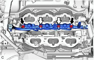
|
|
Bolt |
|
|
Nut |
NOTICE:
- If fuel intrudes into the combustion chamber, there may be adverse affects to the engine main body.
- Make sure not to touch or strike the tips of the fuel injector assemblies.
- Pull and remove the fuel delivery pipe RH in a straight line without tilting it.
|
(d) Disconnect the 3 fuel injector assembly connectors. |
|
6. REMOVE FUEL INJECTOR ASSEMBLY
|
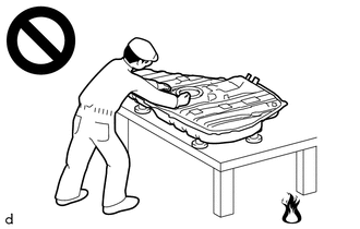
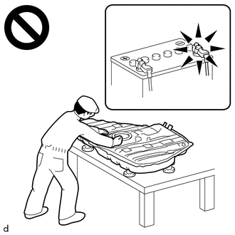
(a) Secure the fuel delivery pipe with sensor assembly LH and fuel delivery pipe RH in a vise between aluminum plates and pull out the 6 fuel injector assemblies. NOTICE:
|
|
(b) Remove the nozzle holder clamp from each fuel injector assembly.
(c) Using needle nose pliers, remove the No. 3 fuel injector back-up ring from each fuel injector assembly.
NOTICE:
Do not damage the area that contacts the O-ring.
(d) Remove the O-ring and No. 1 fuel injector back-up ring from each fuel injector assembly.
(e) Remove the C-ring and injector vibration insulator from each fuel injector assembly.
7. REMOVE FUEL INJECTOR SEAL
|
(a) Using the tip of needle nose pliers, pinch and pull the fuel injector seal at several points to stretch it. NOTICE:
|
|
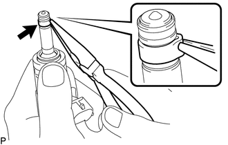
(b) Remove the fuel injector seal from each fuel injector assembly.
|
|
|