| Last Modified: 11-20-2023 | 6.11:8.1.0 | Doc ID: RM10000000158LG |
| Model Year Start: 2018 | Model: Camry | Prod Date Range: [06/2017 - 09/2019] |
| Title: SEAT BELT: SEAT BELT WARNING SYSTEM: TERMINALS OF ECU; 2018 - 2019 MY Camry [06/2017 - 09/2019] | ||
TERMINALS OF ECU
CHECK MAIN BODY ECU (MULTIPLEX NETWORK BODY ECU) AND INSTRUMENT PANEL JUNCTION BLOCK ASSEMBLY
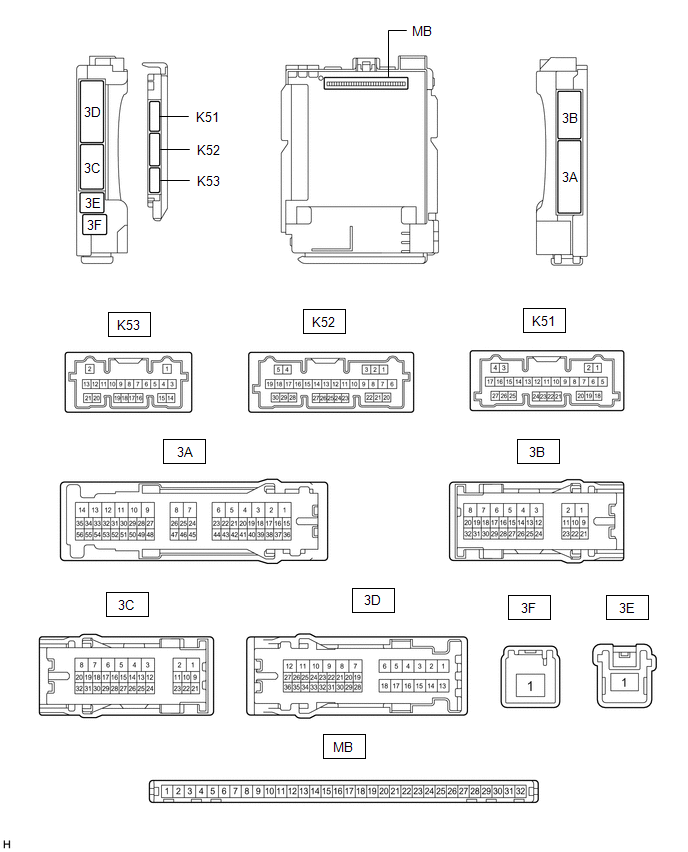
(a) Disconnect the instrument panel junction block assembly and main body ECU (multiplex network body ECU) connectors.
Click here
![2018 - 2020 MY Camry [06/2017 - 10/2020]; POWER DISTRIBUTION: MAIN BODY ECU: REMOVAL](/t3Portal/stylegraphics/info.gif)
(b) Reconnect the instrument panel junction block assembly connectors.
(c) Measure the resistance and voltage according to the value(s) in the table below.
HINT:
Measure the values on the wire harness side with the connector disconnected.
|
Terminal No. (Symbol) |
Wiring Color |
Terminal Description |
Condition |
Specified Condition |
|---|---|---|---|---|
|
MB-31 (BECU) - Body ground |
- |
Battery power supply |
Always |
11 to 14 V |
|
MB-32 (IG) - Body ground |
- |
Ignition power supply (IG signal) |
Ignition switch ON |
11 to 14 V |
|
Ignition switch off |
Below 1 V |
|||
|
MB-30 (ACC) - Body ground |
- |
Ignition power supply (ACC signal) |
Ignition switch ACC |
11 to 14 V |
|
Ignition switch off |
Below 1 V |
|||
|
MB-11 (GND1) - Body ground |
- |
Ground |
Always |
Below 1 Ω |
|
MB-2 (RCTY) - Body ground |
- |
Rear door courtesy light switch RH input |
Rear door LH closed (OFF) |
10 kΩ or higher |
|
Rear door LH open (ON) |
Below 1 Ω |
|||
|
MB-13 (LCTY) - Body ground |
- |
Rear door courtesy light switch LH input |
Rear door RH closed (OFF) |
10 kΩ or higher |
|
Rear door RH open (ON) |
Below 1 Ω |
CHECK COMBINATION METER ASSEMBLY
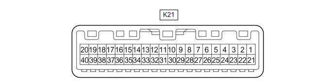
(a) Disconnect the K21 combination meter assembly connector.
(b) Measure the resistance and voltage according to the value(s) in the table below.
HINT:
Measure the values on the wire harness side with the connector disconnected.
|
Terminal No. (Symbol) |
Wiring Color |
Terminal Description |
Condition |
Specified Condition |
|---|---|---|---|---|
|
K21-40 (B) - Body ground |
LA-B - Body ground |
Battery power supply |
Always |
11 to 14 V |
|
K21-39 (IG+) - Body ground |
LA-GR Body ground |
Ignition power supply |
Ignition switch off |
Below 1 V |
|
Ignition switch ON |
11 to 14 V |
|||
|
K21-21 (ES) - Body ground |
W-B - Body ground |
Ground |
Always |
Below 1 Ω |
|
K21-24 (RLSB) - Body ground |
SB - Body ground |
Rear LH seat belt buckle switch signal |
Rear LH seat belt fastened |
10 kΩ or higher |
|
Rear LH seat belt unfastened |
Below 1 Ω |
|||
|
K21-26 (RRSB) - Body ground |
LG - Body ground |
Rear RH seat belt buckle switch signal |
Rear RH seat belt fastened |
10 kΩ or higher |
|
Rear RH seat belt unfastened |
Below 1 Ω |
|||
|
K21-25 (RCSB) - Body ground |
B - Body ground |
Rear center seat belt buckle switch signal |
Rear center seat belt fastened |
10 kΩ or higher |
|
Rear center seat belt unfastened |
Below 1 Ω |
(c) Reconnect the K21 combination meter assembly connector.
(d) Measure the voltage according to the value(s) in the table below.
|
Terminal No. (Symbol) |
Wiring Color |
Terminal Description |
Condition |
Specified Condition |
|---|---|---|---|---|
|
K21-18 (RLMT) - Body ground |
BE - Body ground |
Rear LH seat belt warning light output signal |
Ignition switch ON, rear seat belt warning light (LH) off |
11 to 14 V |
|
Ignition switch ON, rear seat belt warning light (LH) on |
Below 1 V |
|||
|
K21-20 (RRMT) - Body ground |
G - Body ground |
Rear center seat belt warning light output signal |
Ignition switch ON, rear seat belt warning light (center) off |
11 to 14 V |
|
Ignition switch ON, rear seat belt warning light (center) on |
Below 1 V |
|||
|
K21-19 (RCMT) - Body ground |
R - Body ground |
Rear RH seat belt warning light output signal |
Ignition switch ON, rear seat belt warning light (RH) off |
11 to 14 V |
|
Ignition switch ON, rear seat belt warning light (RH) on |
Below 1 V |
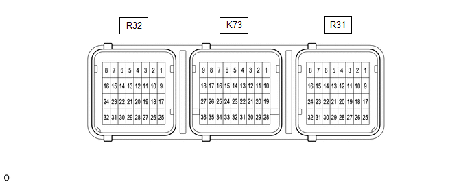
AIRBAG SENSOR ASSEMBLY
|
Terminal No. |
Terminal Symbol |
Destination |
|---|---|---|
|
R32-28 |
LBE+ |
Front seat inner belt assembly LH |
|
R32-27 |
LBE- |
Front seat inner belt assembly LH |
CHECK OCCUPANT DETECTION ECU (for TMC Made)

(a) Measure the voltage and check for pulses according to the value(s) in the table below.
|
Terminal No. (Symbol) |
Wiring Color |
Terminal Description |
Condition |
Specified Condition |
|---|---|---|---|---|
|
a2-10 (GND) - Body ground |
W-B - Body ground |
Ground |
Always |
Below 1 V |
|
a2-6 (IG2) - a2-10 (GND) |
B - W-B |
Power source |
Ignition switch ON |
11 to 14 V |
|
a2-9 (BGND) - a2-10 (GND) |
P - W-B |
Front passenger buckle switch ground |
Always |
Below 1 V |
|
a2-7 (BSW) - a2-9 (BGND) |
G - P |
Front passenger buckle switch signal |
Always |
Pulse generation |
|
a1-1 (SVC1) - a1-5 (SGD1) |
R - G |
Front occupant classification sensor LH power supply |
Ignition switch ON |
11 to 14 V |
|
a1-2 (SVC3) - a1-6 (SGD3) |
GR - W |
Rear occupant classification sensor LH power supply |
Ignition switch ON |
11 to 14 V |
|
a1-3 (SIG1) - a1-5 (SGD1) |
P - G |
Front occupant classification sensor LH signal |
Ignition switch ON |
Pulse generation |
|
a1-4 (SIG3) - a1-6 (SGD3) |
SB - W |
Rear occupant classification sensor LH signal |
Ignition switch ON |
Pulse generation |
|
a1-5 (SGD1) - a2-10 (GND) |
G - W-B |
Front occupant classification sensor LH ground |
Always |
Below 1 V |
|
a1-6 (SGD3) - a2-10 (GND) |
W - W-B |
Rear occupant classification sensor LH ground |
Always |
Below 1 V |
CHECK OCCUPANT DETECTION ECU (for TMMK Made)

(a) Measure the voltage and check for pulses according to the value(s) in the table below.
|
Terminal No. (Symbol) |
Wiring Color |
Terminal Description |
Condition |
Specified Condition |
|---|---|---|---|---|
|
a6-10 (GND) - Body ground |
W-B - Body ground |
Ground |
Always |
Below 1 V |
|
a6-6 (IG) - a6-10 (GND) |
B - W-B |
Power source |
Ignition switch ON |
11 to 14 V |
|
a6-9 (BGND) - a6-10 (GND) |
P - W-B |
Front passenger buckle switch ground |
Always |
Below 1 V |
|
a6-7 (BSW) - a6-9 (BGND) |
G - P |
Front passenger buckle switch signal |
Always |
Pulse generation |
|
a7-1 (SVC1) - a7-5 (SGD1) |
R - G |
Front occupant classification sensor LH power supply |
Ignition switch ON |
11 to 14 V |
|
a7-2 (SVC3) - a7-6 (SGD3) |
GR - W |
Rear occupant classification sensor LH power supply |
Ignition switch ON |
11 to 14 V |
|
a7-3 (SIG1) - a7-5 (SGD1) |
P - G |
Front occupant classification sensor LH signal |
Ignition switch ON |
Pulse generation |
|
a7-4 (SIG3) - a7-6 (SGD3) |
SB - W |
Rear occupant classification sensor LH signal |
Ignition switch ON |
Pulse generation |
|
a7-5 (SGD1) - a6-10 (GND) |
G - W-B |
Front occupant classification sensor LH ground |
Always |
Below 1 V |
|
a7-6 (SGD3) - a6-10 (GND) |
W - W-B |
Rear occupant classification sensor LH ground |
Always |
Below 1 V |
|
|
|