| Last Modified: 09-09-2025 | 6.11:8.1.0 | Doc ID: RM10000000155U9 |
| Model Year Start: 2018 | Model: Camry | Prod Date Range: [06/2017 - 10/2020] |
| Title: BRAKE CONTROL / DYNAMIC CONTROL SYSTEMS: VEHICLE STABILITY CONTROL SYSTEM (w/o Electric Parking Brake System): TERMINALS OF ECU; 2018 - 2020 MY Camry [06/2017 - 10/2020] | ||
TERMINALS OF ECU
TERMINALS OF ECU

|
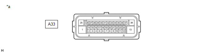
*a |
Component without harness connected (Skid Control ECU (Brake Actuator Assembly)) |
- |
- |
|
Terminal No. (Symbol) |
Terminal Description |
|---|---|
|
1 (+BM) |
ABS motor relay power supply |
|
2 (SP1) |
Speed signal output for speedometer |
|
3 (STPO)* |
Stop light control relay (stop light switch assembly) output |
|
4 (FR-) |
Front wheel speed RH (-) signal input |
|
5 |
- |
|
6 |
- |
|
7 |
- |
|
8 (FL-) |
Front wheel speed LH (-) signal input |
|
9 (CSW) |
VSC OFF switch input |
|
10 |
- |
|
11 |
- |
|
12 |
- |
|
13 (GND2) |
Pump motor ground |
|
14 (CANL) |
CAN communication line L |
|
15 |
- |
|
16 (FR+) |
Front wheel speed RH (+) signal input |
|
17 (RR+) |
Rear wheel speed RH (+) signal input |
|
18 (RL-) |
Rear wheel speed LH (-) signal input |
|
19 (FL+) |
Front wheel speed LH (+) signal input |
|
20 |
- |
|
21 |
- |
|
22 (STP2)* |
Stop light control relay (stop light switch assembly) input |
|
23 |
- |
|
24 |
- |
|
25 (+BS) |
ABS solenoid relay power supply |
|
26 (CANH) |
CAN communication line H |
|
27 |
- |
|
28 (IG1) |
IG1 power source input |
|
29 (RR-) |
Rear wheel speed RH (-) signal input |
|
30 (STP) |
Stop light switch assembly input |
|
31 (RL+) |
Rear wheel speed LH (+) signal input |
|
32 |
- |
|
33 |
- |
|
34 |
- |
|
35 |
- |
|
36 |
- |
|
37 |
- |
|
38 (GND1) |
Skid control ECU (brake actuator assembly) ground |
- *: w/ Pre-collision System
TERMINAL INSPECTION
(a) Disconnect the connector and measure the voltage and resistance on the wire harness side.
|
*a |
Front view of wire harness connector (to Skid Control ECU (Brake Actuator Assembly)) |
- |
- |
HINT:
The voltage cannot be measured with the connector connected to the skid control ECU (brake actuator assembly) because the connector is watertight.
Standard
|
Terminal No. (Symbol) |
Wiring Color |
Terminal Description |
Condition |
Specified Condition |
|---|---|---|---|---|
|
A33-1 (+BM) - Body ground |
B - Body ground |
ABS motor relay power supply |
Always |
11 to 14 V |
|
A33-3 (STPO) - Body ground*2 |
L - Body ground |
Stop light control relay (stop light switch assembly) output |
Always |
11 to 14 V |
|
A33-9 (CSW) - Body ground |
P - Body ground |
VSC OFF switch input |
VSC OFF switch on → off (Pressed → not pressed) |
Below 1 Ω → 10 kΩ or higher |
|
A33-13 (GND2) - Body ground |
W-B - Body ground |
Pump motor ground |
Always |
Below 1 Ω |
|
A33-22 (STP2) - Body ground*2 |
R - Body ground |
Stop light control relay (stop light switch assembly) input |
Stop light switch assembly on → off (Brake pedal depressed → released) |
(+BS x 0.85) to 14 V*1 → Below 1.5 V |
|
A33-25 (+BS) - Body ground |
L - Body ground |
ABS solenoid relay power supply |
Always |
11 to 14 V |
|
A33-28 (IG1) - Body ground |
B - Body ground |
IG1 power source input |
Ignition switch ON |
11 to 14 V |
|
A33-30 (STP) - Body ground |
GR - Body ground |
Stop light switch assembly input |
Stop light switch assembly on → off (Brake pedal depressed → released) |
(+BS x 0.85) to 14 V*1 → Below 1.5 V |
|
A33-38 (GND1) - Body ground |
W-B - Body ground |
Skid control ECU (brake actuator assembly) ground |
Always |
Below 1 Ω |
- *1: The minimum voltage value varies depending on the +BS terminal voltage value. The minimum voltage is 85% or more of the +BS terminal voltage.
- *2: w/ Pre-collision System
|
|
|