| 
                     
                        | Last Modified: 11-20-2023 | 6.11:8.1.0 | Doc ID: RM10000000155SK |  
                        | Model Year Start: 2018 | Model: Camry | Prod Date Range: [06/2017 - 10/2020] |  
                        | Title: BRAKE CONTROL / DYNAMIC CONTROL SYSTEMS: VEHICLE STABILITY CONTROL SYSTEM (w/ Electric Parking Brake System): C1428; Motor Circuit Malfunction; 2018 - 2020 MY Camry [06/2017 - 10/2020] |  
                     
                        
                           | DTC | C1428 | Motor Circuit Malfunction |  DESCRIPTIONThis DTC is stored when the skid control ECU (brake actuator assembly) judges that an abnormality occurred in the circuit used to operate the pump motor. 


                           | DTC No. | Detection Item | DTC Detection Condition | Trouble Area |  
                           | C1428 | Motor Circuit Malfunction | A malfunction occurs in the pump motor circuit. | Pump motor circuit |  WIRING DIAGRAMRefer to DTC C146C. Click here
                        
                           
                              ![2018 - 2020 MY Camry [06/2017 - 10/2020]; BRAKE CONTROL / DYNAMIC CONTROL SYSTEMS: VEHICLE STABILITY CONTROL SYSTEM (w/ Electric Parking Brake System): C146C; Open in ABS Motor Relay Circuit](/t3Portal/stylegraphics/info.gif)  CAUTION / NOTICE / HINT
                     NOTICE: 
                        
When replacing the skid control ECU (brake actuator assembly), perform system variant learning and acceleration sensor zero point calibration.
Click here
                                 
                                    
                                       ![2018 - 2020 MY Camry [06/2017 - 10/2020]; BRAKE CONTROL / DYNAMIC CONTROL SYSTEMS: VEHICLE STABILITY CONTROL SYSTEM (w/ Electric Parking Brake System): CALIBRATION](/t3Portal/stylegraphics/info.gif) 
Inspect the fuses for circuits related to this system before performing the following procedure.
 PROCEDURE
                     
                        
                           | 1.  | CHECK HARNESS AND CONNECTOR (+BM TERMINAL) |  
                     
                        
                           | (a) Make sure that there is no looseness at the locking part and the connecting part of the connector. OK:  The connector is securely connected. | 
                                 
                                    |   |  
                                    | 


                                                | *a | Front view of wire harness connector (to Skid Control ECU (Brake Actuator Assembly)) |  |  |  
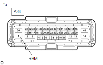
(b) Disconnect the A34 skid control ECU (brake actuator assembly) connector. (c) Check both the connector case and the terminals for deformation and corrosion. OK:  No deformation or corrosion. (d) Measure the voltage according to the value(s) in the table below. Standard Voltage:  


                           | Tester Connection | Condition | Specified Condition |  
                           | A34-1 (+BM) - Body ground | Always | 11 to 14 V |  
                     
                        
                           | NG |   | REPAIR OR REPLACE HARNESS OR CONNECTOR (+BM CIRCUIT) |  
                     
                        | 
                              
                                 | OK |  
                                 |   |  |  
                     
                        
                           | 2.  | 
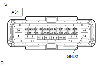
CHECK HARNESS AND CONNECTOR (GND2 TERMINAL) |  
                     
                        
                           | (a) Measure the resistance according to the value(s) in the table below. Standard Resistance:  


                                       | Tester Connection | Condition | Specified Condition |  
                                       | A34-14 (GND2) - Body ground | Always | Below 1 Ω |  | 
                                 
                                    |   |  
                                    | 


                                                | *a | Front view of wire harness connector (to Skid Control ECU (Brake Actuator Assembly)) |  |  |  
                     
                        
                           | NG |   | REPAIR OR REPLACE HARNESS OR CONNECTOR (GND2 CIRCUIT) |  
                     
                        | 
                              
                                 | OK |  
                                 |   |  |  (a) Reconnect the A34 skid control ECU (brake actuator assembly) connector. (b) Clear the DTCs. Chassis > ABS/VSC/TRAC/EPB > Clear DTCs(c) Turn the engine switch off. (d) Start the engine. (e) Perform a road test. (f) Check if the same DTC is output. Chassis > ABS/VSC/TRAC/EPB > Trouble Codes
                     
                        
                           | Result | Proceed to |  
                           | C1428 is not output | A |  
                           | C1428 is output | B |  |