- (With the exception of the switch indicators, no inputs are reflected when other switches operated)
| Last Modified: 09-09-2025 | 6.11:8.1.0 | Doc ID: RM1000000013PZG |
| Model Year Start: 2018 | Model: Camry | Prod Date Range: [03/2017 - 10/2020] |
| Title: HEATING / AIR CONDITIONING: AIR CONDITIONING SYSTEM (for Automatic Air Conditioning System): Operation not Accepted Even If Air Conditioning Switch is Operated; 2018 - 2020 MY Camry [03/2017 - 10/2020] | ||
|
Operation not Accepted Even If Air Conditioning Switch is Operated |
DESCRIPTION
If the air conditioning system cannot be operated using the air conditioning control panel (radio and display receiver assembly)*1 or air conditioning control assembly*2, the following suspected areas may be the cause.
|
Symptom |
Factor |
|---|---|
|
Air conditioning system cannot be operated using air conditioning control panel (radio and display receiver assembly)*1 or air conditioning control assembly*2 |
|
- *1: for 8 Inch Display
- *2: for 7 Inch Display
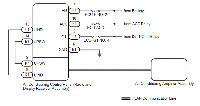
WIRING DIAGRAM
for 8 Inch Display
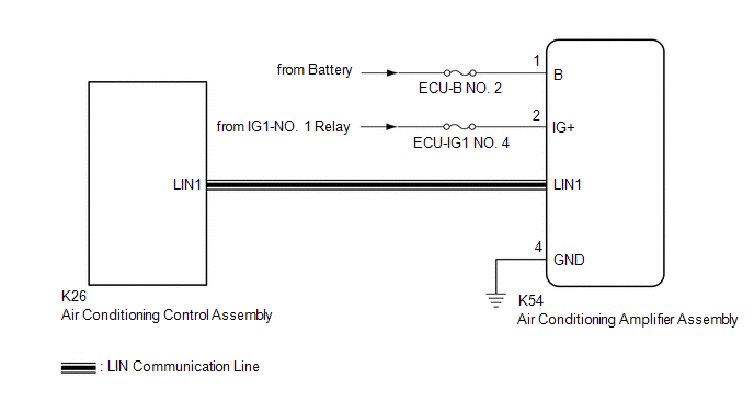
for 7 Inch Display
PROCEDURE
PROCEDURE
|
1. |
CONFIRM MODEL |
|
Result |
Proceed to |
|---|---|
|
for 8 Inch Display |
A |
|
for 7 Inch Display |
B |
| B |

|
|

|
2. |
CHECK HARNESS AND CONNECTOR (RADIO AND DISPLAY RECEIVER ASSEMBLY - POWER SOURCE AND BODY GROUND) |
(a) Disconnect the h1 air conditioning control panel (radio and display receiver assembly) connector.
(b) Measure the resistance according to the value(s) in the table below.
Standard Resistance:
|
Tester Connection |
Condition |
Specified Condition |
|---|---|---|
|
h1-6 (GND) - Body ground |
Always |
Below 1 Ω |
(c) Measure the voltage according to the value(s) in the table below.
Standard Voltage:
|
Tester Connection |
Condition |
Specified Condition |
|---|---|---|
|
h1-3 (+B) - Body ground |
Power switch off |
11 to 14 V |
|
h1-10 (ACC) - Body ground |
Power switch on (ACC) |
11 to 14 V |
|
h1-2 (IG1) - Body ground |
Power switch on (IG) |
11 to 14 V |
| NG |
|
REPAIR OR REPLACE HARNESS OR CONNECTOR |
|
|
3. |
CHECK FOR DTC (AUDIO AND VISUAL SYSTEM) |
(a) Check for DTCs.
Body Electrical > Navigation System > Trouble Codes
OK:
DTC B15F9 is not output.
| NG |
|
REPLACE AIR CONDITIONING CONTROL PANEL (RADIO AND DISPLAY RECEIVER ASSEMBLY) Click here
|
|
|
4. |
CHECK FOR DTC (CAN COMMUNICATION SYSTEM) |
(a) Using the Techstream, check for CAN communication system DTCs.
Click here
![2018 - 2024 MY Camry [03/2017 - ]; NETWORKING: CAN COMMUNICATION SYSTEM: DIAGNOSTIC TROUBLE CODE CHART](/t3Portal/stylegraphics/info.gif)
|
Result |
Proceed to |
|---|---|
|
CAN communication system DTCs are not output |
A |
|
CAN communication system DTCs are output |
B |
| B |
|
|
|
5. |
PERFORM ACTIVE TEST USING TECHSTREAM |
(a) Connect the Techstream to the DLC3.
(b) Turn the ignition switch to ON.
(c) Turn the Techstream on.
(d) Enter the following menus: Body Electrical / Air Conditioner / Active Test.
(e) Perform the Active Test according to the display on the Techstream.
Body Electrical > Air Conditioner > Active Test
|
Tester Display |
Measurement Item |
Control Range |
Diagnostic Note |
|---|---|---|---|
|
Blower Motor |
Blower motor with fan sub-assembly |
Min.: 0 Max.: 31 |
- |
Body Electrical > Air Conditioner > Active Test
|
Tester Display |
|---|
|
Blower Motor |
OK:
Blower motor with fan sub-assembly operates normally.
| OK |
|
REPLACE AIR CONDITIONING CONTROL PANEL (RADIO AND DISPLAY RECEIVER ASSEMBLY) Click here
|
| NG |
|
REPLACE AIR CONDITIONING AMPLIFIER ASSEMBLY Click here
|
|
6. |
CHECK FOR DTC |
(a) Check for DTCs.
Body Electrical > Air Conditioner > Trouble Codes
OK:
DTC B14B2 is not output.
| NG |
|
|
|
7. |
CHECK HARNESS AND CONNECTOR (AIR CONDITIONING AMPLIFIER ASSEMBLY - BATTERY AND BODY GROUND) |
|
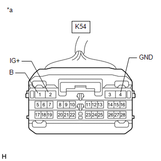
*a |
Front view of wire harness connector (to Air Conditioning Amplifier Assembly) |
(a) Disconnect the K54 air conditioning amplifier assembly connector.
(b) Measure the resistance according to the value(s) in the table below.
Standard Resistance:
|
Tester Connection |
Condition |
Specified Condition |
|---|---|---|
|
K54-4 (GND) - Body ground |
Always |
Below 1 Ω |
(c) Measure the voltage according to the value(s) in the table below.
Standard Voltage:
|
Tester Connection |
Switch Condition |
Specified Condition |
|---|---|---|
|
K54-1 (B) - Body ground |
Always |
11 to 14 V |
|
K54-2 (IG+) - Body ground |
Ignition switch ON |
11 to 14 V |
|
Ignition switch off |
Below 1 V |
| OK |
|
REPLACE AIR CONDITIONING AMPLIFIER ASSEMBLY Click here
|
| NG |
|
REPAIR OR REPLACE HARNESS OR CONNECTOR |
|
|
|