| Last Modified: 09-09-2025 | 6.11:8.1.0 | Doc ID: RM1000000013PZF |
| Model Year Start: 2018 | Model: Camry | Prod Date Range: [03/2017 - ] |
| Title: HEATING / AIR CONDITIONING: AIR CONDITIONING SYSTEM (for Automatic Air Conditioning System): Pressure Sensor Circuit; 2018 - 2024 MY Camry [03/2017 - ] | ||
|
Pressure Sensor Circuit |
DESCRIPTION
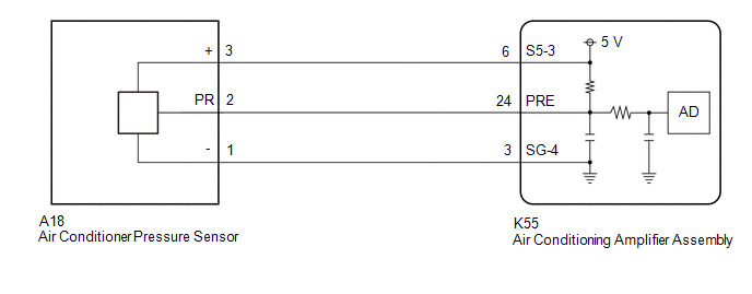
Based on signals from the air conditioner pressure sensor, the air conditioning amplifier assembly controls the compressor assembly with pulley (compressor solenoid)*1 or cooler compressor assembly (compressor solenoid)*2 and changes the air inlet mode between fresh and recirculation in order to protect the parts of the refrigerant cycle.
- *1: for A25A-FKS
- *2: for 2GR-FKS
WIRING DIAGRAM
PROCEDURE
PROCEDURE
|
1. |
CHECK HARNESS AND CONNECTOR (POWER SOURCE CIRCUIT) |
|
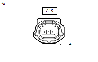
*a |
Front view of wire harness connector (to Air Conditioner Pressure Sensor) |
(a) Disconnect the A18 air conditioner pressure sensor connector.
(b) Measure the voltage according to the value(s) in the table below.
Standard Voltage:
|
Tester Connection |
Condition |
Specified Condition |
|---|---|---|
|
A18-3 (+) - Body ground |
Ignition switch ON |
4.75 to 5.25 V |
| NG |

|
|

|
2. |
CHECK HARNESS AND CONNECTOR (AIR CONDITIONER PRESSURE SENSOR - BODY GROUND) |
|
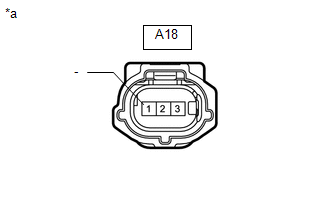
*a |
Front view of wire harness connector (to Air Conditioner Pressure Sensor) |
(a) Measure the resistance according to the value(s) in the table below.
Standard Resistance:
|
Tester Connection |
Condition |
Specified Condition |
|---|---|---|
|
A18-1 (-) - Body ground |
Always |
Below 1 Ω |
| NG |
|
|
|
3. |
CHECK HARNESS AND CONNECTOR (AIR CONDITIONER PRESSURE SENSOR - AIR CONDITIONING AMPLIFIER ASSEMBLY) |
(a) Disconnect the K55 air conditioning amplifier assembly connector.
(b) Measure the resistance according to the value(s) in the table below.
Standard Resistance:
|
Tester Connection |
Condition |
Specified Condition |
|---|---|---|
|
A18-2 (PR) - K55-24 (PRE) |
Always |
Below 1 Ω |
|
A18-2 (PR) or K55-24 (PRE) - Other terminals and body ground |
Always |
10 kΩ or higher |
| NG |
|
REPAIR OR REPLACE HARNESS OR CONNECTOR |
|
|
4. |
INSPECT AIR CONDITIONER PRESSURE SENSOR (SENSOR SIGNAL CIRCUIT) |
|
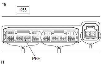
*a |
Component with harness connected (Air Conditioning Amplifier Assembly) |
(a) Measure the voltage with the following conditions met.
Measurement Condition:
|
Item |
Condition |
|---|---|
|
Vehicle doors |
Fully open |
|
Temperature setting |
MAX COLD |
|
Blower speed |
HI |
|
A/C switch |
On |
|
Recirculation/fresh switch |
RECIRCULATION |
|
Interior temperature |
25 to 35°C (77 to 95°F) |
NOTICE:
- If refrigerant pressure on the high pressure side becomes extremely high during the inspection (if the voltage exceeds 4.61 V), a fail-safe function will stop compressor operation. In this case, make sure to measure the voltage before the fail-safe function operates.
- It is necessary to measure the voltage for a certain amount of time (approximately 10 minutes) because the malfunction may recur after a while.
HINT:
When the ambient air temperature is low (below -1.5°C (29.3°F)), the compressor with pulley will be stopped, due to inputs of the thermistor assembly and No. 1 cooler thermistor, to prevent the evaporator from freezing. In this case, perform the inspection in a warm indoor environment.
(1) Measure the voltage according to the value(s) in the table below.
Standard Voltage:
|
Tester Connection |
Condition |
Specified Condition |
|---|---|---|
|
K55-24 (PRE) - Body ground |
Ignition switch ON (A/C switch: On) |
0.74 to 4.61 V |
(b) Connect the Techstream to the DLC3.
(c) Turn the ignition switch to ON.
(d) Turn the Techstream on.
(e) Enter the following menus: Body Electrical / Air Conditioner / Data List.
(f) Read the Data List according to the display on the Techstream.
Body Electrical > Air Conditioner > Data List
|
Tester Display |
Measurement Item |
Range |
Normal Condition |
Diagnostic Note |
|---|---|---|---|---|
|
Regulator Pressure Sensor |
Air conditioner pressure sensor |
Min.: -456.68 kPaG Max.: 3294.37 kPaG |
Actual refrigerant pressure displayed |
- |
Body Electrical > Air Conditioner > Data List
|
Tester Display |
|---|
|
Regulator Pressure Sensor |
OK:
The voltage and value displayed in the Data List change.
|
Result |
Proceed to |
|---|---|
|
OK |
A |
|
NG (The voltage changes but the value displayed in the Data List does not change.) |
|
|
NG (The voltage does not change.) |
B |
| A |
|
REPLACE AIR CONDITIONING AMPLIFIER ASSEMBLY Click here
|
![2018 MY Camry [03/2017 - 06/2017]; HEATING / AIR CONDITIONING: AIR CONDITIONING AMPLIFIER: REMOVAL](/t3Portal/stylegraphics/info.gif)
| B |
|
REPLACE AIR CONDITIONER PRESSURE SENSOR Click here
|
|
5. |
CHECK HARNESS AND CONNECTOR (AIR CONDITIONER PRESSURE SENSOR - AIR CONDITIONING AMPLIFIER ASSEMBLY) |
(a) Disconnect the K55 air conditioning amplifier assembly connector.
(b) Measure the resistance according to the value(s) in the table below.
Standard Resistance:
|
Tester Connection |
Condition |
Specified Condition |
|---|---|---|
|
K55-3 (SG-4) - A18-1 (-) |
Always |
Below 1 Ω |
|
K55-3 (SG-4) or A18-1 (-) - Other terminals and body ground |
Always |
10 kΩ or higher |
| OK |
|
REPLACE AIR CONDITIONING AMPLIFIER ASSEMBLY Click here
|
| NG |
|
REPAIR OR REPLACE HARNESS OR CONNECTOR |
|
6. |
CHECK HARNESS AND CONNECTOR (AIR CONDITIONER PRESSURE SENSOR - AIR CONDITIONING AMPLIFIER ASSEMBLY) |
(a) Disconnect the K55 air conditioning amplifier assembly connector.
(b) Measure the resistance according to the value(s) in the table below.
Standard Resistance:
|
Tester Connection |
Condition |
Specified Condition |
|---|---|---|
|
K55-6 (S5-3) - A18-3 (+) |
Always |
Below 1 Ω |
|
K55-6 (S5-3) or A18-3 (+) - Other terminals and body ground |
Always |
10 kΩ or higher |
| OK |
|
REPLACE AIR CONDITIONING AMPLIFIER ASSEMBLY Click here
|
| NG |
|
REPAIR OR REPLACE HARNESS OR CONNECTOR |
|
|
|