| Last Modified: 11-20-2023 | 6.11:8.1.0 | Doc ID: RM10000000134QD |
| Model Year Start: 2018 | Model: Camry | Prod Date Range: [03/2017 - ] |
| Title: DOOR LOCK: WIRELESS DOOR LOCK CONTROL SYSTEM (w/o Smart Key System): No Answer-Back; 2018 - 2024 MY Camry [03/2017 - ] | ||
|
No Answer-Back |
DESCRIPTION
In some cases, wireless door lock control functions are normal but the hazard warning light and wireless door lock buzzer answer-back functions do not operate. In such cases, hazard warning light and wireless door lock buzzer signal outputs from the main body ECU (multiplex network body ECU) may be malfunctioning.
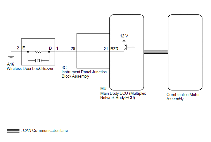
WIRING DIAGRAM
CAUTION / NOTICE / HINT
NOTICE:
The wireless door lock control system uses the CAN communication system. Inspect the communication function by following How to Proceed with Troubleshooting. Troubleshoot the wireless door lock control system after confirming that the communication system is functioning properly.
Click here
![2018 - 2024 MY Camry [03/2017 - ]; DOOR LOCK: WIRELESS DOOR LOCK CONTROL SYSTEM (w/o Smart Key System): HOW TO PROCEED WITH TROUBLESHOOTING](/t3Portal/stylegraphics/info.gif)
PROCEDURE
|
1. |
READ VALUE USING TECHSTREAM (Hazard Answer Back, Wireless Buzzer Resp, Wireless Buzzer Vol) |
(a) Connect the Techstream to the DLC3.
(b) Turn the ignition switch to ON.
(c) Turn the Techstream on.
(d) Enter the following menus: Customize Setting / Wireless Door Lock.
(e) Select the setting by referring to the table below.
Wireless Door Lock
|
Tester Display |
Description |
Default |
Setting |
ECU |
|---|---|---|---|---|
|
Hazard Answer Back |
Function that flashes the hazard warning lights once when the doors are locked by wireless operation and twice when the doors are unlocked by wireless operation |
ON |
0:OFF,1:ON |
Main body ECU (Multiplex network body ECU) |
|
Wireless Buzzer Resp |
Function that enables/disables the wireless door lock buzzer response |
ON |
0:OFF,1:ON |
Main body ECU (Multiplex network body ECU) |
|
Wireless Buzzer Vol |
Function that adjusts the wireless door lock buzzer volume |
Level5 |
0000:Level7,0001:Level6,0010:Level5,0011:Level4,0100:Level3,0101:Level2,0110:Level1,0111:Level0 |
Main body ECU (Multiplex network body ECU) |
|
Result |
Proceed to |
|---|---|
|
Both items are ON and except Level0 |
A |
|
Either item is OFF or Level0 |
B |
| B |

|
|

|
2. |
CHECK WIRELESS DOOR LOCK CONTROL FUNCTIONS |
(a) Check the wireless door lock control function using the door control transmitter module set sub-assembly.
|
Result |
Proceed to |
|---|---|
|
Wireless door lock/unlock operates properly |
A |
|
Wireless door lock/unlock does not operate properly |
B |
| B |
|
|
|
3. |
READ VALUE USING TECHSTREAM (FR Door Lock Pos, FL Door Lock Pos, RR-Door Lock Pos SW, RL-Door Lock Pos SW) |
(a) Connect the Techstream to the DLC3.
(b) Turn the ignition switch to ON.
(c) Turn the Techstream on.
(d) Enter the following menus: Body Electrical / Main Body / Data List.
(e) Read the Data List according to the display on the Techstream.
Body Electrical > Main Body > Data List
|
Tester Display |
Measurement Item |
Range |
Normal Condition |
Diagnostic Note |
|---|---|---|---|---|
|
FR Door Lock Pos |
Front door RH unlock detection switch signal |
LOCK or UNLOCK |
LOCK: Front door RH locked UNLOCK: Front door RH unlocked |
- |
|
FL Door Lock Pos |
Front door LH unlock detection switch signal |
LOCK or UNLOCK |
LOCK: Front door LH locked UNLOCK: Front door LH unlocked |
- |
|
RR-Door Lock Pos SW |
Rear door RH unlock detection switch signal |
OFF or ON |
OFF: Rear door RH locked ON: Rear door RH unlocked |
- |
|
RL-Door Lock Pos SW |
Rear door RH unlock detection switch signal |
OFF or ON |
OFF: Rear door LH locked ON: Rear door LH unlocked |
- |
Body Electrical > Main Body > Data List
|
Tester Display |
|---|
|
FR Door Lock Pos |
|
FL Door Lock Pos |
|
RR-Door Lock Pos SW |
|
RL-Door Lock Pos SW |
OK:
The Techstream display changes correctly in response to the lock/unlock operation.
| NG |
|
GO TO LIGHTING SYSTEM (Proceed to Door Unlock Detection Switch Circuit) |
|
|
4. |
CHECK WIRELESS ANSWER-BACK OPERATION |
(a) Check the wireless answer-back operation using the door control transmitter module set sub-assembly.
|
Result |
Proceed to |
|---|---|
|
Only wireless door lock buzzer answer-back does not occur |
A |
|
Only hazard warning light answer-back does not occur |
B |
| B |
|
|
|
5. |
INSPECT WIRELESS DOOR LOCK BUZZER |
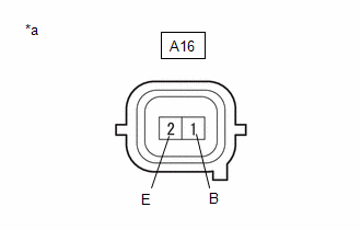
(a) Disconnect the A16 wireless door lock buzzer connector.
|
(b) Measure the voltage according to the value(s) in the table below. Standard Voltage:
|
|
| NG |
|
|
|
6. |
PERFORM ACTIVE TEST USING TECHSTREAM (Wireless Buzzer) |
(a) Connect the Techstream to the DLC3.
(b) Turn the ignition switch to ON.
(c) Turn the Techstream on.
(d) Enter the following menus: Body Electrical / Main Body / Active Test.
(e) Perform the Active Test according to the display on the Techstream.
Body Electrical > Main Body > Active Test
|
Tester Display |
Measurement Item |
Control Range |
Restrict Condition |
|---|---|---|---|
|
Wireless Buzzer |
Wireless door lock buzzer |
OFF/ON |
- |
Body Electrical > Main Body > Active Test
|
Tester Display |
|---|
|
Wireless Buzzer |
|
Result |
Proceed to |
|---|---|
|
Wireless door lock buzzer does not turn on/off |
A |
|
Wireless door lock buzzer turns on/off |
B |
| B |
|
REPLACE MAIN BODY ECU (MULTIPLEX NETWORK BODY ECU)
|
|
|
7. |
CHECK HARNESS AND CONNECTOR (WIRELESS DOOR LOCK BUZZER - INSTRUMENT PANEL JUNCTION BLOCK ASSEMBLY) |
(a) Disconnect the A16 wireless door lock buzzer connector.
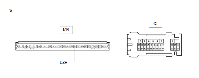
(b) Disconnect the 3C instrument panel junction block assembly connector.
(c) Measure the resistance according to the value(s) in the table below.
Standard Resistance:
|
Tester Connection |
Condition |
Specified Condition |
|---|---|---|
|
A16-1 (B) - 3C-29 |
Always |
Below 1 Ω |
|
A16-2 (E) - Body ground |
Always |
Below 1 Ω |
|
A16-1 (B) or 3C-29 - Body ground |
Always |
10 kΩ or higher |
| NG |
|
REPAIR OR REPLACE HARNESS OR CONNECTOR |
|
|
8. |
INSPECT INSTRUMENT PANEL JUNCTION BLOCK ASSEMBLY |
(a) Remove the instrument panel junction block assembly.
Click here
|
*a |
Component without harness connected (Instrument Panel Junction Block Assembly) |
- |
- |
(b) Remove the main body ECU (multiplex network body ECU) from the instrument panel junction block assembly.
(c) Measure the resistance according to the value(s) in the table below.
Standard Resistance:
|
Tester Connection |
Condition |
Specified Condition |
|---|---|---|
|
3C-29 - MB-21 (BZR) |
Always |
Below 1 Ω |
| NG |
|
REPLACE INSTRUMENT PANEL JUNCTION BLOCK ASSEMBLY
|
|
|
9. |
REPLACE WIRELESS DOOR LOCK BUZZER |
(a) Temporarily replace the wireless door lock buzzer with a new one.
Click here
|
|
10. |
CHECK WIRELESS DOOR LOCK BUZZER OPERATION |
(a) Check the operation of the wireless answer-back function.
Click here
OK:
Wireless answer-back function operates normally.
| OK |
|
END (WIRELESS DOOR LOCK BUZZER WAS DEFECTIVE) |
| NG |
|
REPLACE MAIN BODY ECU (MULTIPLEX NETWORK BODY ECU)
|
|
11. |
CHECK HAZARD WARNING LIGHTS OPERATION |
(a) Check that the hazard warning lights blink when the hazard warning signal switch is pressed.
OK:
Hazard warning lights blink.
| OK |
|
REPLACE MAIN BODY ECU (MULTIPLEX NETWORK BODY ECU)
|
| NG |
|
GO TO LIGHTING SYSTEM (Proceed to Hazard Warning Switch Circuit)
|
|
|
|