| Last Modified: 11-20-2023 | 6.11:8.1.0 | Doc ID: RM10000000134OI |
| Model Year Start: 2018 | Model: Camry | Prod Date Range: [03/2017 - ] |
| Title: THEFT DETERRENT / KEYLESS ENTRY: THEFT DETERRENT SYSTEM: Unlock Warning Switch Circuit; 2018 - 2024 MY Camry [03/2017 - ] | ||
|
Unlock Warning Switch Circuit |
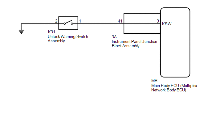
DESCRIPTION
The unlock warning switch assembly turns on when the key is inserted into the ignition key cylinder and turns off when the key is removed.
WIRING DIAGRAM
PROCEDURE
|
1. |
READ VALUE USING TECHSTREAM (KEY UNLOCK WARNING SW) |
(a) Connect the Techstream to the DLC3.
(b) Turn the ignition switch to ON.
(c) Turn the Techstream on.
(d) Enter the following menus: Body Electrical / Main Body / Data List.
(e) Read the Data List according to the display on the Techstream.
Body Electrical > Main Body > Data List
|
Tester Display |
Measurement Item |
Range |
Normal Condition |
Diagnostic Note |
|---|---|---|---|---|
|
Key Unlock Warning SW |
Unlock warning switch |
OFF or ON |
OFF: Ignition key not inserted ON: Ignition key inserted |
- |
Body Electrical > Main Body > Data List
|
Tester Display |
|---|
|
Key Unlock Warning SW |
OK:
The Techstream display changes correctly in response to the unlock warning switch assembly status.
| OK |

|
PROCEED TO NEXT SUSPECTED AREA SHOWN IN PROBLEM SYMPTOMS TABLE
|
|

|
2. |
INSPECT UNLOCK WARNING SWITCH ASSEMBLY |
(a) Remove the unlock warning switch assembly.
Click here
![2018 - 2024 MY Camry [03/2017 - ]; DOOR LOCK: UNLOCK WARNING SWITCH: REMOVAL](/t3Portal/stylegraphics/info.gif)
(b) Inspect the unlock warning switch assembly.
Click here
| NG |
|
|
|
3. |
INSPECT INSTRUMENT PANEL JUNCTION BLOCK ASSEMBLY |
(a) Remove the main body ECU (multiplex network body ECU).
Click here
|
*a |
Component without harness connected (Instrument Panel Junction Block Assembly) |
- |
- |
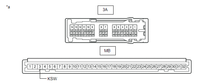
(b) Disconnect the 3A instrument panel junction block assembly connector.
(c) Measure the resistance according to the value(s) in the table below.
Standard Resistance:
|
Tester Connection |
Condition |
Specified Condition |
|---|---|---|
|
3A-41 - MB-3 (KSW) |
Always |
Below 1 Ω |
| NG |
|
REPLACE INSTRUMENT PANEL JUNCTION BLOCK ASSEMBLY
|
|
|
4. |
CHECK HARNESS AND CONNECTOR (INSTRUMENT PANEL JUNCTION BLOCK ASSEMBLY - UNLOCK WARNING SWITCH ASSEMBLY - BODY GROUND) |
(a) Measure the resistance according to the value(s) in the table below.
Standard Resistance:
|
Tester Connection |
Condition |
Specified Condition |
|---|---|---|
|
3A-41 - K31-1 |
Always |
Below 1 Ω |
|
3A-41 or K31-1 - Other terminals and body ground |
Always |
10 kΩ or higher |
|
K31-2 - Body ground |
Always |
Below 1 Ω |
| OK |
|
REPLACE MAIN BODY ECU (MULTIPLEX NETWORK BODY ECU)
|
| NG |
|
REPAIR OR REPLACE HARNESS OR CONNECTOR |
|
|
|