| Last Modified: 11-20-2023 | 6.11:8.1.0 | Doc ID: RM1000000012UO2 |
| Model Year Start: 2018 | Model: Camry | Prod Date Range: [03/2017 - 06/2017] |
| Title: METER / GAUGE / DISPLAY: METER / GAUGE SYSTEM: Speedometer Malfunction; 2018 MY Camry [03/2017 - 06/2017] | ||
|
Speedometer Malfunction |
DESCRIPTION
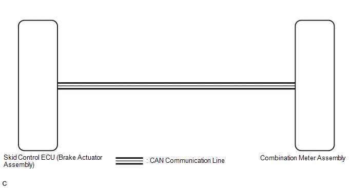
The combination meter assembly receives vehicle speed signals from the skid control ECU (brake actuator assembly) via CAN communication. The speed sensor detects the wheel speed and sends the appropriate signals to the skid control ECU (brake actuator assembly). The skid control ECU (brake actuator assembly) supplies power to the vehicle speed sensor. The skid control ECU (brake actuator assembly) detects vehicle speed signals based on pulses of the voltage.
HINT:
Factors that affect the indicated vehicle speed include the tire size, tire inflation, and tire wear. The speed indicated on the speedometer has an allowable margin of error.
WIRING DIAGRAM
CAUTION / NOTICE / HINT
NOTICE:
- When replacing the combination meter assembly, always replace it with a new one. If a combination meter assembly which was installed to another vehicle is used, the information stored in it will not match the information from the vehicle and a DTC may be stored.
-
Before starting the following inspection, inspect the speedometer and check that the tire size and air pressure are as specified.
Tire size and air pressure: Click here
![2018 MY Camry [03/2017 - 06/2017]; TIRE / WHEEL: TIRE AND WHEEL SYSTEM: INSPECTION](/t3Portal/stylegraphics/info.gif)
Speedometer: Click here
PROCEDURE
|
1. |
CHECK CAN COMMUNICATION SYSTEM |
(a) Check if CAN communication DTCs are output.
Click here
|
Result |
Proceed to |
|---|---|
|
DTCs are not output |
A |
|
DTCs are output |
B |
| B |

|
|

|
2. |
CHECK FOR DTC (VEHICLE STABILITY CONTROL SYSTEM) |
(a) Check if vehicle stability control system DTCs are output.
Chassis > ABS/VSC/TRAC > Trouble Codes
|
Result |
Proceed to |
|---|---|
|
DTCs are not output |
A |
|
DTCs are output |
B |
| B |
|
|
|
3. |
PERFORM ACTIVE TEST USING TECHSTREAM (SPEEDOMETER OPERATION) |
(a) Connect the Techstream to the DLC3.
(b) Turn the ignition switch to ON.
(c) Turn the Techstream on.
(d) Enter the following menus: Body Electrical / Combination Meter / Active Test.
(e) Perform the Active Test according to the display on the Techstream.
Body Electrical > Combination Meter > Active Test
|
Tester Display |
Measurement Item |
Control Range |
Diagnostic Note |
|---|---|---|---|
|
Speedometer Operation (0km/h,0MPH) |
Speedometer 0km/h (0mph) |
OFF or ON |
- |
|
Speedometer Operation (40km/h,40MPH) |
Speedometer 40 km/h (40 mph) |
OFF or ON |
The value displayed on the speedometer may deviate. Reference mph: 40 → 39.5 to 42.3 |
|
Speedometer Operation (80km/h,80MPH) |
Speedometer 80 km/h (80 mph) |
OFF or ON |
The value displayed on the speedometer may deviate. Reference mph: 80 → 80.2 to 83.4 |
|
Speedometer Operation (120km/h,120MPH) |
Speedometer 120 km/h (120 mph) |
OFF or ON |
The value displayed on the speedometer may deviate. Reference mph: 120 → 121.1 to 124.3 |
Body Electrical > Combination Meter > Active Test
|
Tester Display |
|---|
|
Speedometer Operation (0km/h,0MPH) |
Body Electrical > Combination Meter > Active Test
|
Tester Display |
|---|
|
Speedometer Operation (40km/h,40MPH) |
Body Electrical > Combination Meter > Active Test
|
Tester Display |
|---|
|
Speedometer Operation (80km/h,80MPH) |
Body Electrical > Combination Meter > Active Test
|
Tester Display |
|---|
|
Speedometer Operation (120km/h,120MPH) |
OK:
Speedometer indication is normal.
| OK |
|
| NG |
|
|
|
|