| Last Modified: 11-20-2023 | 6.11:8.1.0 | Doc ID: RM1000000012UHB |
| Model Year Start: 2018 | Model: Camry | Prod Date Range: [03/2017 - 06/2017] |
| Title: LIGHTING (INT): LIGHTING SYSTEM: Interior Light Circuit; 2018 MY Camry [03/2017 - 06/2017] | ||
|
Interior Light Circuit |
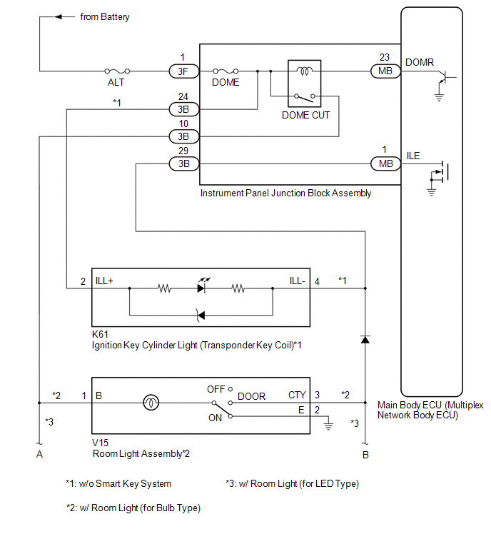
DESCRIPTION
The main body ECU (multiplex network body ECU) controls the operation of the following lights:
- Ignition Key Cylinder Light (Transponder Key Coil)*1
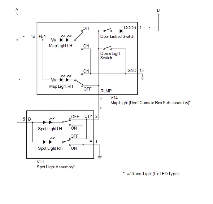
- Map Light (Roof Console Box Sub-assembly)*2
- Spot Light Assembly*2
- Room Light Assembly*3
- *1: w/o Smart Key System
- *2: w/ Room Light (for LED Type)
- *3: w/ Room Light (for Bulb Type)
WIRING DIAGRAM
CAUTION / NOTICE / HINT
NOTICE:
- Inspect the fuses for circuits related to this system before performing the following procedure.
-
Before replacing the main body ECU (multiplex network body ECU), refer to Registration.*
Click here
![2018 - 2019 MY Camry [03/2017 - 09/2019]; THEFT DETERRENT / KEYLESS ENTRY: SMART KEY SYSTEM (for Start Function): REGISTRATION](/t3Portal/stylegraphics/info.gif)
- *: w/ Smart Key System
HINT:
The DOME CUT relay supplies power to the interior lights. If all the lights that use power from the DOME CUT relay do not turn on, check the interior light auto cut circuit first.
Click here
PROCEDURE
|
1. |
PERFORM ACTIVE TEST USING TECHSTREAM |
(a) Connect the Techstream to the DLC3.
(b) Turn the ignition switch to ON.
(c) Turn the Techstream on.
(d) Enter the following menus: Body Electrical / Main Body / Active Test.
(e) Perform the Active Test according to the display on the Techstream.
Body Electrical > Main Body > Active Test
|
Tester Display |
Measurement Item |
Control Range |
Diagnostic Note |
|---|---|---|---|
|
Illuminated Entry System |
Turns on the lights that are controlled by the illuminated entry system* |
OFF or ON |
w/ Room Light (for LED Type): Perform the Active Test with the door linked switch of the map light (roof console box sub-assembly) on and switches of the spot light assembly LH and RH off. w/ Room Light (for Bulb Type): Perform the Active Test with switch of the room light assembly in the DOOR position. |
-
*: Refer to System Description for the lights that are controlled by the illuminated entry system.
Click here
Body Electrical > Main Body > Active Test
|
Tester Display |
|---|
|
Illuminated Entry System |
OK:
All lights that are controlled by the illuminated entry system come on.
|
Result |
Proceed to |
|---|---|
|
OK |
A |
|
NG (Map light (roof console box sub-assembly) and/or spot light assembly do not come on (w/ Room Light (for LED Type))) |
B |
|
NG (Room light assembly does not come on (w/ Room Light (for Bulb Type))) |
C |
|
NG (Ignition key cylinder light (transponder key coil) does not come on) |
D |
|
NG (All lights that are controlled by the illuminated entry system do not come on) |
E |
| A |

|
PROCEED TO NEXT SUSPECTED AREA SHOWN IN PROBLEM SYMPTOMS TABLE |
| C |
|
| D |
|
| E |
|
|

|
2. |
INSPECT MAP LIGHT (ROOF CONSOLE BOX SUB-ASSEMBLY) |
(a) Remove the map light (roof console box sub-assembly).
Click here
(b) Inspect the map light (roof console box sub-assembly).
Click here
| NG |
|
|
|
3. |
INSPECT SPOT LIGHT ASSEMBLY |
(a) Remove the spot light assembly.
Click here
(b) Inspect the spot light assembly.
Click here
| NG |
|
|
|
4. |
CHECK HARNESS AND CONNECTOR (MAP LIGHT (ROOF CONSOLE BOX SUB-ASSEMBLY) - SPOT LIGHT ASSEMBLY) |
(a) Measure the resistance according to the value(s) in the table below.
Standard Resistance:
|
Tester Connection |
Condition |
Specified Condition |
|---|---|---|
|
V14-14 (+B1) - V11-5 (B) |
Always |
Below 1 Ω |
|
V14-2 (RLMP) - V11-2 (CTY) |
Always |
Below 1 Ω |
|
V14-14 (+B1) or V11-5 (B) - Body ground |
Always |
10 kΩ or higher |
|
V14-2 (RLMP) or V11-2 (CTY) - Body ground |
Always |
10 kΩ or higher |
| NG |
|
REPAIR OR REPLACE HARNESS OR CONNECTOR |
|
|
5. |
CHECK HARNESS AND CONNECTOR (INSTRUMENT PANEL JUNCTION BLOCK ASSEMBLY - MAP LIGHT (ROOF CONSOLE BOX SUB-ASSEMBLY)) |
(a) Disconnect the 3B instrument panel junction block assembly connector.
(b) Connect the V14 map light (roof console box sub-assembly) connector.
(c) Apply battery voltage to the connector and check that the map light comes on.
OK:
|
Measurement Condition |
Condition |
Specified Condition |
|---|---|---|
|
Battery positive (+) → 3B-10 Battery negative (-) → 3B-29 |
Door linked switch on and map light switch LH and RH off |
Map light LH and RH come on |
| OK |
|
| NG |
|
REPAIR OR REPLACE HARNESS OR CONNECTOR |
|
6. |
CHECK HARNESS AND CONNECTOR (INSTRUMENT PANEL JUNCTION BLOCK ASSEMBLY - INSTRUMENT PANEL JUNCTION BLOCK ASSEMBLY) |
(a) Disconnect the 3B instrument panel junction block assembly connector.
(b) Apply battery voltage to the connector and check that the room light comes on.
OK:
|
Measurement Condition |
Condition |
Specified Condition |
|---|---|---|
|
Battery positive (+) → 3B-10 Battery negative (-) → 3B-29 |
Room light switch in DOOR position |
Room light comes on |
| OK |
|
| NG |
|
REPAIR OR REPLACE HARNESS OR CONNECTOR (INCLUDING BULB HOLDER OF THE ROOM LIGHT ASSEMBLY THAT ARE PART OF THE WIRE HARNESS) |
|
7. |
INSPECT IGNITION KEY CYLINDER LIGHT (TRANSPONDER KEY COIL) |
(a) Remove the ignition key cylinder light (transponder key coil).
Click here
(b) Inspect the ignition key cylinder light (transponder key coil).
Click here
| NG |
|
|
|
8. |
CHECK HARNESS AND CONNECTOR (BATTERY - INSTRUMENT PANEL JUNCTION BLOCK ASSEMBLY) |
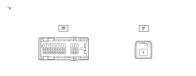
(a) Disconnect the 3F instrument panel junction block assembly connector.
(b) Measure the voltage according to the value(s) in the table below.
Standard Voltage:
|
Tester Connection |
Condition |
Specified Condition |
|---|---|---|
|
3F-1 - Body ground |
Always |
11 to 14 V |
| NG |
|
REPAIR OR REPLACE HARNESS OR CONNECTOR |
|
|
9. |
INSPECT INSTRUMENT PANEL JUNCTION BLOCK ASSEMBLY |
|
*a |
Component without harness connected (Instrument Panel Junction Block Assembly) |
- |
- |
(a) Disconnect the 3B instrument panel junction block assembly connector.
(b) Measure the resistance according to the value(s) in the table below.
Standard Resistance:
|
Tester Connection |
Condition |
Specified Condition |
|---|---|---|
|
3B-24 - 3F-1 |
Always |
Below 1 Ω |
| NG |
|
|
|
10. |
CHECK HARNESS AND CONNECTOR (IGNITION KEY CYLINDER LIGHT (TRANSPONDER KEY COIL) - INSTRUMENT PANEL JUNCTION BLOCK ASSEMBLY) |
(a) Measure the resistance according to the value(s) in the table below.
Standard Resistance:
|
Tester Connection |
Condition |
Specified Condition |
|---|---|---|
|
K61-2 (ILL+) - 3B-24 |
Always |
Below 1 Ω |
|
K61-4 (ILL-) - 3B-29 |
||
|
K61-2 (ILL+) or 3B-24 - Body ground |
Always |
10 kΩ or higher |
|
K61-4 (ILL-) or 3B-29 - Body ground |
| OK |
|
| NG |
|
REPAIR OR REPLACE HARNESS OR CONNECTOR |
|
11. |
INSPECT INSTRUMENT PANEL JUNCTION BLOCK ASSEMBLY |
|
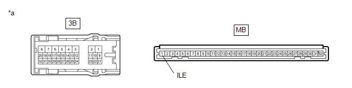
*a |
Component without harness connected (Instrument Panel Junction Block Assembly) |
- |
- |
(a) Remove the instrument panel junction block assembly.
Click here
(b) Remove the main body ECU (multiplex network body ECU) from the instrument panel junction block assembly.
Click here
(c) Measure the resistance according to the value(s) in the table below.
Standard Resistance:
|
Tester Connection |
Condition |
Specified Condition |
|---|---|---|
|
3B-29 - MB-1 (ILE) |
Always |
Below 1 Ω |
| OK |
|
| NG |
|
|
|
|