| Last Modified: 09-09-2025 | 6.11:8.1.0 | Doc ID: RM1000000012SYN |
| Model Year Start: 2018 | Model: Camry | Prod Date Range: [03/2017 - 06/2017] |
| Title: BRAKE CONTROL / DYNAMIC CONTROL SYSTEMS: VEHICLE STABILITY CONTROL SYSTEM: Brake Warning Light Remains ON; 2018 MY Camry [03/2017 - 06/2017] | ||
|
Brake Warning Light Remains ON |
DESCRIPTION
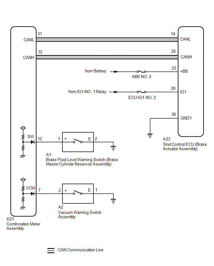
The skid control ECU (brake actuator assembly) is connected to the combination meter assembly via CAN communication.
If any of the following is detected, the brake warning light remains on:
- The skid control ECU (brake actuator assembly) connector is disconnected from the skid control ECU (brake actuator assembly).
- The brake fluid level is insufficient.
- The vacuum inside the brake booster decreases.
- EBD operation is not possible.
WIRING DIAGRAM
CAUTION / NOTICE / HINT
NOTICE:
-
When replacing the skid control ECU (brake actuator assembly), perform system variant learning and acceleration sensor zero point calibration.
Click here
![2018 MY Camry [03/2017 - 06/2017]; BRAKE CONTROL / DYNAMIC CONTROL SYSTEMS: VEHICLE STABILITY CONTROL SYSTEM: CALIBRATION](/t3Portal/stylegraphics/info.gif)
- Inspect the fuses for circuits related to this system before performing the following procedure.
- Before performing this procedure, depress the brake pedal and confirm that the stop lights illuminate.
PROCEDURE
PROCEDURE
|
1. |
CHECK CAN COMMUNICATION SYSTEM |
(a) Check if CAN communication system DTCs are output.
Click here
|
Result |
Proceed to |
|---|---|
|
DTCs are not output |
A |
|
DTCs are output |
B |
| B |

|
|

|
2. |
CHECK IF BRAKE ACTUATOR ASSEMBLY CONNECTOR IS SECURELY CONNECTED |
(a) Check if the skid control ECU (brake actuator assembly) connector is securely connected.
OK:
The connector is securely connected.
| NG |
|
CONNECT CONNECTOR TO BRAKE ACTUATOR ASSEMBLY CORRECTLY |
|
|
3. |
CHECK BATTERY |
(a) Check the battery voltage.
Standard Voltage:
|
Tester Connection |
Condition |
Specified Condition |
|---|---|---|
|
Positive (+) terminal - Negative (-) terminal |
Ignition switch off |
11 to 14 V |
| NG |
|
|
|
4. |
CHECK HARNESS AND CONNECTOR (POWER SOURCE TERMINAL) |
|
(a) Turn the ignition switch off. |
|
(b) Make sure that there is no looseness at the locking part and the connecting part of the connector.
OK:
The connector is securely connected.
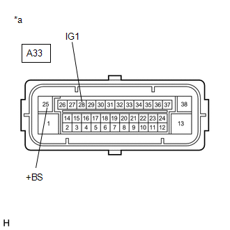
(c) Disconnect the A33 skid control ECU (brake actuator assembly) connector.
(d) Check both the connector case and the terminals for deformation and corrosion.
OK:
No deformation or corrosion.
(e) Measure the voltage according to the value(s) in the table below.
Standard Voltage:
|
Tester Connection |
Condition |
Specified Condition |
|---|---|---|
|
A33-25 (+BS) - Body ground |
Always |
11 to 14 V |
|
A33-28 (IG1) - Body ground |
Ignition switch ON |
11 to 14 V |
| NG |
|
REPAIR OR REPLACE HARNESS OR CONNECTOR (POWER SOURCE CIRCUIT) |
|
|
5. |
CHECK HARNESS AND CONNECTOR (GND1 TERMINAL) |
|
(a) Turn the ignition switch off. |
|
(b) Measure the resistance according to the value(s) in the table below.
Standard Resistance:
|
Tester Connection |
Condition |
Specified Condition |
|---|---|---|
|
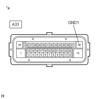
A33-38 (GND1) - Body ground |
Always |
Below 1 Ω |
| NG |
|
REPAIR OR REPLACE HARNESS OR CONNECTOR (GND1 CIRCUIT) |
|
|
6. |
INSPECT BRAKE MASTER CYLINDER RESERVOIR ASSEMBLY |
|
(a) Turn the ignition switch off. |
|
(b) Reconnect the A33 skid control ECU (brake actuator assembly) connector.
(c) Remove the reservoir filler cap and strainer.
(d) Make sure that there is no looseness at the locking part and the connecting part of the connector.
OK:
The connector is securely connected.
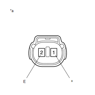
(e) Disconnect the A1 brake fluid level warning switch (brake master cylinder reservoir assembly) connector.
(f) Check both the connector case and the terminals for deformation and corrosion.
OK:
No deformation or corrosion.
(g) Measure the resistance according to the value(s) in the table below.
HINT:
A float is located inside the reservoir. Its position changes according to the brake fluid level.
Standard Resistance:
|
Tester Connection |
Condition |
Specified Condition |
|---|---|---|
|
1 (+) - 2 (E) |
Switch off (float up) |
1.9 to 2.1 kΩ |
|
1 (+) - 2 (E) |
Switch on (float down) |
Below 1 Ω |
HINT:
If there is no problem after finishing the above check, adjust the brake fluid level to the MAX level.
| NG |
|
|
|
7. |
CHECK HARNESS AND CONNECTOR (COMBINATION METER ASSEMBLY - BRAKE MASTER CYLINDER RESERVOIR ASSEMBLY) |
(a) Make sure that there is no looseness at the locking part and the connecting part of the connector.
OK:
The connector is securely connected.
(b) Disconnect the K21 combination meter assembly connector.
(c) Check both the connector case and the terminals for deformation and corrosion.
OK:
No deformation or corrosion.
(d) Measure the resistance according to the value(s) in the table below.
Standard Resistance:
|
Tester Connection |
Condition |
Specified Condition |
|---|---|---|
|
K21-12 (SW) - A1-1 (+) |
Always |
Below 1 Ω |
|
K21-12 (SW) or A1-1 (+) - Body ground |
Always |
10 kΩ or higher |
|
A1-2 (E) - Body ground |
Always |
Below 1 Ω |
| NG |
|
REPAIR OR REPLACE HARNESS OR CONNECTOR |
|
|
8. |
INSPECT VACUUM WARNING SWITCH ASSEMBLY |
(a) Reconnect the A1 brake fluid level warning switch (brake master cylinder reservoir assembly) connector.
(b) Reconnect the K21 combination meter assembly connector.
(c) Inspect the vacuum warning switch assembly.
Click here
OK:
The vacuum warning switch assembly is normal.
| NG |
|
REPLACE VACUUM WARNING SWITCH ASSEMBLY |
|
|
9. |
CHECK HARNESS AND CONNECTOR (COMBINATION METER ASSEMBLY - VACUUM WARNING SWITCH ASSEMBLY) |
(a) Make sure that there is no looseness at the locking part and the connecting part of the connector.
OK:
The connector is securely connected.
(b) Disconnect the A2 vacuum warning switch assembly connector.
(c) Disconnect the K21 combination meter assembly connector.
(d) Check both the connector case and the terminals for deformation and corrosion.
OK:
No deformation or corrosion.
(e) Measure the resistance according to the value(s) in the table below.
Standard Resistance:
|
Tester Connection |
Condition |
Specified Condition |
|---|---|---|
|
K21-7 (VCM) - A2-2 (+) |
Always |
Below 1 Ω |
|
K21-7 (VCM) or A2-2 (+) - Body ground |
Always |
10 kΩ or higher |
|
A2-1 (E) - Body ground |
Always |
Below 1 Ω |
| NG |
|
REPAIR OR REPLACE HARNESS OR CONNECTOR |
|
|
10. |
READ VALUE USING TECHSTREAM (BRAKE WARNING LIGHT) |
(a) Reconnect the A2 vacuum warning switch assembly connector.
(b) Reconnect the K21 combination meter assembly connector.
(c) Enter the following menus: Chassis / ABS/VSC/TRAC / Data List.
Chassis > ABS/VSC/TRAC > Data List
|
Tester Display |
Measurement Item |
Range |
Normal Condition |
Diagnostic Note |
|---|---|---|---|---|
|
Brake Warning Light |
Brake warning light |
ON or OFF |
ON: Warning light on OFF: Warning light off |
- |
Chassis > ABS/VSC/TRAC > Data List
|
Tester Display |
|---|
|
Brake Warning Light |
(d) Check the Techstream display condition of the brake warning light.
|
Result |
Proceed to |
|---|---|
|
The value of Brake Warning Light is ON |
A |
|
The value of Brake Warning Light is OFF |
B |
| A |
|
| B |
|
|
|
|