| Last Modified: 11-20-2023 | 6.11:8.1.0 | Doc ID: RM1000000012SYG |
| Model Year Start: 2018 | Model: Camry | Prod Date Range: [03/2017 - 06/2017] |
| Title: BRAKE CONTROL / DYNAMIC CONTROL SYSTEMS: VEHICLE STABILITY CONTROL SYSTEM: C1249; Open in Stop Light Switch Circuit; 2018 MY Camry [03/2017 - 06/2017] | ||
|
DTC |
C1249 |
Open in Stop Light Switch Circuit |
DESCRIPTION
The skid control ECU (brake actuator assembly) receives stop light switch assembly signals and uses them to determine whether or not the brakes are applied. DTCs may be stored if either of the following occurs:
- Stop light switch assembly stuck on malfunction.
- The accelerator and brake pedals are depressed simultaneously.*
HINT:
*: The skid control ECU (brake actuator assembly) may store this DTC upon judging that a stuck on malfunction has occurred when the accelerator pedal and brake pedal are depressed simultaneously. However, this does not indicate a malfunction.
|
DTC No. |
Detection Item |
DTC Detection Condition |
Trouble Area |
|---|---|---|---|
|
C1249 |
Open in Stop Light Switch Circuit |
The vehicle speed is 10 km/h (6 mph) or more, the accelerator pedal is depressed, the master cylinder pressure is 0.5 MPa (5.09 kgf/cm2, 72 psi) or less, and the stop light switch assembly is on for 60 seconds or more. |
|
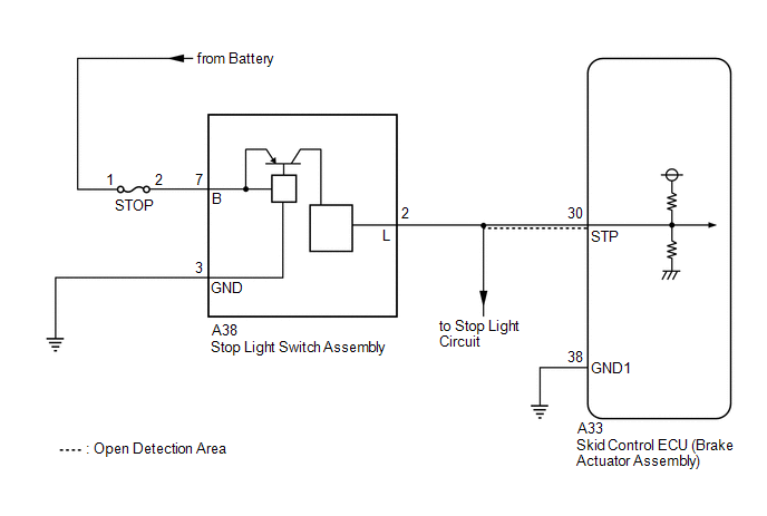
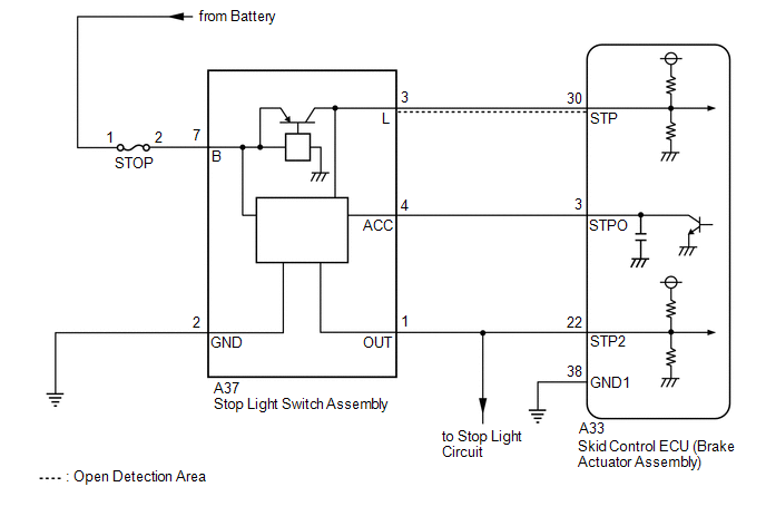
WIRING DIAGRAM
w/o Pre-collision System:
w/ Pre-collision System:
CAUTION / NOTICE / HINT
NOTICE:
-
When replacing the skid control ECU (brake actuator assembly), perform system variant learning and acceleration sensor zero point calibration.
Click here
![2018 MY Camry [03/2017 - 06/2017]; BRAKE CONTROL / DYNAMIC CONTROL SYSTEMS: VEHICLE STABILITY CONTROL SYSTEM: CALIBRATION](/t3Portal/stylegraphics/info.gif)
- Inspect the fuses for circuits related to this system before performing the following procedure.
PROCEDURE
|
1. |
READ VALUE USING TECHSTREAM (BS1 VOLTAGE VALUE) |
(a) Connect the Techstream to the DLC3.
(b) Turn the ignition switch to ON.
(c) Enter the following menus: Chassis / ABS/VSC/TRAC / Data List.
Chassis > ABS/VSC/TRAC > Data List
|
Tester Display |
Measurement Item |
Range |
Normal Condition |
Diagnostic Note |
|---|---|---|---|---|
|
BS1 Voltage Value |
+BS voltage value |
Min.: 0.00 V, Max.: 20.00 V |
- |
Changes in proportion to battery voltage |
Chassis > ABS/VSC/TRAC > Data List
|
Tester Display |
|---|
|
BS1 Voltage Value |
(d) Take a note of the +BS voltage value.
HINT:
The noted +BS voltage value is used in a later step.
|

|
2. |
CHECK ACCELERATOR PEDAL AND BRAKE PEDAL OPERATION |
(a) Interview the customer to check if the pedals were depressed simultaneously while driving or braking.
OK:
The pedals were not depressed simultaneously.
HINT:
The skid control ECU (brake actuator assembly) may store this DTC upon judging that a stuck on malfunction has occurred when the accelerator pedal and brake pedal are depressed simultaneously.
If the pedals were depressed simultaneously, clear the DTC because it is not a malfunction.
|
Result |
Proceed to |
|---|---|
|
OK (w/o Pre-collision System) |
A |
|
OK (w/ Pre-collision System) |
B |
|
NG |
C |
| B |

|
| C |
|
|
|
3. |
CHECK STOP LIGHT OPERATION |
(a) Check that the stop lights come on when the brake pedal is depressed, and go off when the brake pedal is released.
OK:
|
Condition |
Illumination Condition |
|---|---|
|
Brake pedal depressed |
On |
|
Brake pedal released |
Off |
| NG |
|
|
|
4. |
READ VALUE USING TECHSTREAM (STOP LIGHT SWITCH ASSEMBLY) |
(a) Connect the Techstream to the DLC3.
(b) Turn the ignition switch to ON.
(c) Enter the following menus: Chassis / ABS/VSC/TRAC / Data List.
Chassis > ABS/VSC/TRAC > Data List
|
Tester Display |
Measurement Item |
Range |
Normal Condition |
Diagnostic Note |
|---|---|---|---|---|
|
Stop Light SW |
Stop light switch assembly |
ON or OFF |
ON: Brake pedal depressed OFF: Brake pedal released |
- |
Chassis > ABS/VSC/TRAC > Data List
|
Tester Display |
|---|
|
Stop Light SW |
(d) Check that the stop light switch assembly display observed on the Techstream changes according to brake pedal operation.
OK:
The Techstream displays on or off according to brake pedal operation.
| NG |
|
|
|
5. |
RECONFIRM DTC |
(a) Clear the DTCs.
Chassis > ABS/VSC/TRAC > Clear DTCs
(b) Turn the ignition switch off.
(c) Start the engine.
(d) Drive the vehicle and depress the brake pedal several times to test the stop light circuit.
(e) Check if the same DTC is output.
Chassis > ABS/VSC/TRAC > Trouble Codes
|
Result |
Proceed to |
|---|---|
|
C1249 is not output |
A |
|
C1249 is output |
B |
| A |
|
| B |
|
|
6. |
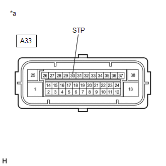
CHECK HARNESS AND CONNECTOR (STP TERMINAL) |
|
(a) Turn the ignition switch off. |
|
(b) Make sure that there is no looseness at the locking part and the connecting part of the connector.
OK:
The connector is securely connected.
(c) Disconnect the A33 skid control ECU (brake actuator assembly) connector.
(d) Check both the connector case and the terminals for deformation and corrosion.
OK:
No deformation or corrosion.
(e) Measure the voltage according to the value(s) in the table below.
Standard Voltage:
|
Tester Connection |
Condition |
Specified Condition |
|---|---|---|
|
A33-30 (STP) - Body ground |
Stop light switch assembly on (Brake pedal depressed) |
(+BS x 0.85) to 14 V* |
|
A33-30 (STP) - Body ground |
Stop light switch assembly off (Brake pedal released) |
Below 1.5 V |
HINT:
*: The minimum voltage value varies depending on the +BS terminal voltage value. The minimum voltage is 85% or more of the +BS terminal voltage.
| OK |
|
| NG |
|
REPAIR OR REPLACE HARNESS OR CONNECTOR (STP CIRCUIT) |
|
7. |
INSPECT STOP LIGHT SWITCH ASSEMBLY |
(a) Check the stop light switch assembly.
Click here
OK:
The stop light switch assembly is normal.
| NG |
|
|
|
8. |
CHECK HARNESS AND CONNECTOR (STP TERMINAL) |
|
(a) Make sure that there is no looseness at the locking part and the connecting part of the connector. OK: The connector is securely connected. |
|
(b) Disconnect the A33 skid control ECU (brake actuator assembly) connector.
(c) Check both the connector case and the terminals for deformation and corrosion.
OK:
No deformation or corrosion.
(d) Measure the voltage according to the value(s) in the table below.
Standard Voltage:
|
Tester Connection |
Condition |
Specified Condition |
|---|---|---|
|
A33-30 (STP) - Body ground |
Stop light switch assembly on (Brake pedal depressed) |
(+BS x 0.85) to 14 V* |
|
A33-30 (STP) - Body ground |
Stop light switch assembly off (Brake pedal released) |
Below 1.5 V |
HINT:
*: The minimum voltage value varies depending on the +BS terminal voltage value. The minimum voltage is 85% or more of the +BS terminal voltage.
| NG |
|
REPAIR OR REPLACE HARNESS OR CONNECTOR (STP CIRCUIT) |
|
|
9. |
RECONFIRM DTC |
(a) Reconnect the A33 skid control ECU (brake actuator assembly) connector.
(b) Clear the DTCs.
Chassis > ABS/VSC/TRAC > Clear DTCs
(c) Turn the ignition switch off.
(d) Start the engine.
(e) Drive the vehicle and depress the brake pedal several times to test the stop light circuit.
(f) Check if the same DTC is output.
Chassis > ABS/VSC/TRAC > Trouble Codes
|
Result |
Proceed to |
|---|---|
|
C1249 is not output |
A |
|
C1249 is output |
B |
HINT:
If the lighting system is normal but the DTC is still output, replace the skid control ECU (brake actuator assembly).
Click here
| A |
|
| B |
|
|
10. |
INSPECT STOP LIGHT SWITCH ASSEMBLY |
(a) Check the stop light switch assembly.
Click here
OK:
The stop light switch assembly is normal.
| NG |
|
|
|
11. |
READ VALUE USING TECHSTREAM (STOP LIGHT SWITCH ASSEMBLY) |
(a) Connect the Techstream to the DLC3.
(b) Turn the ignition switch to ON.
(c) Enter the following menus: Chassis / ABS/VSC/TRAC / Data List.
Chassis > ABS/VSC/TRAC > Data List
|
Tester Display |
Measurement Item |
Range |
Normal Condition |
Diagnostic Note |
|---|---|---|---|---|
|
Stop Light SW |
Stop light switch assembly |
ON or OFF |
ON: Brake pedal depressed OFF: Brake pedal released |
- |
Chassis > ABS/VSC/TRAC > Data List
|
Tester Display |
|---|
|
Stop Light SW |
(d) Check that the stop light switch assembly display observed on the Techstream changes according to brake pedal operation.
OK:
The Techstream displays on or off according to brake pedal operation.
| NG |
|
|
|
12. |
RECONFIRM DTC |
(a) Clear the DTCs.
Chassis > ABS/VSC/TRAC > Clear DTCs
(b) Turn the ignition switch off.
(c) Start the engine.
(d) Drive the vehicle and depress the brake pedal several times to test the stop light circuit.
(e) Check if the same DTC is output.
Chassis > ABS/VSC/TRAC > Trouble Codes
|
Result |
Proceed to |
|---|---|
|
C1249 is not output |
A |
|
C1249 is output |
B |
| A |
|
| B |
|
|
13. |
CHECK HARNESS AND CONNECTOR (STP TERMINAL) |
|
(a) Turn the ignition switch off. |
|
(b) Make sure that there is no looseness at the locking part and the connecting part of the connector.
OK:
The connector is securely connected.
(c) Disconnect the A33 skid control ECU (brake actuator assembly) connector.
(d) Check both the connector case and the terminals for deformation and corrosion.
OK:
No deformation or corrosion.
(e) Measure the voltage according to the value(s) in the table below.
Standard Voltage:
|
Tester Connection |
Condition |
Specified Condition |
|---|---|---|
|
A33-30 (STP) - Body ground |
Stop light switch assembly on (Brake pedal depressed) |
(+BS x 0.85) to 14 V* |
|
A33-30 (STP) - Body ground |
Stop light switch assembly off (Brake pedal released) |
Below 1.5 V |
HINT:
*: The minimum voltage value varies depending on the +BS terminal voltage value. The minimum voltage is 85% or more of the +BS terminal voltage.
| OK |
|
| NG |
|
REPAIR OR REPLACE HARNESS OR CONNECTOR (STP CIRCUIT) |
|
14. |
CLEAR DTC |
(a) Clear the DTCs.
Chassis > ABS/VSC/TRAC > Clear DTCs
| NEXT |
|
END |
|
|
|