| Last Modified: 09-09-2025 | 6.11:8.1.0 | Doc ID: RM1000000012S8I |
| Model Year Start: 2018 | Model: Camry | Prod Date Range: [03/2017 - 10/2020] |
| Title: CRUISE CONTROL: LANE DEPARTURE ALERT SYSTEM (w/ Steering Control): Power Source Circuit; 2018 - 2020 MY Camry [03/2017 - 10/2020] | ||
|
Power Source Circuit |
DESCRIPTION
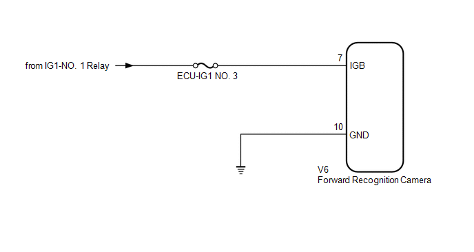
This circuit provides power to operate the forward recognition camera.
WIRING DIAGRAM
CAUTION / NOTICE / HINT
NOTICE:
Inspect the fuses for circuits related to this system before performing the following inspection procedure.
PROCEDURE
PROCEDURE
|
1. |
CHECK HARNESS AND CONNECTOR (POWER SOURCE VOLTAGE) |
|
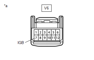
(a) Disconnect the V6 forward recognition camera connector. |
|
(b) Turn the ignition switch to ON.
(c) Measure the voltage according to the value(s) in the table below.
Standard Voltage:
|
Tester Connection |
Condition |
Specified Condition |
|---|---|---|
|
V6-7 (IGB) - Body ground |
Ignition switch ON |
11 to 14 V |
(d) Turn the ignition switch off.
(e) Connect the V6 forward recognition camera connector.
| NG |

|
REPAIR OR REPLACE HARNESS OR CONNECTOR |
|

|
2. |
CHECK HARNESS AND CONNECTOR (FORWARD RECOGNITION CAMERA - BODY GROUND) |
|
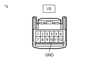
(a) Disconnect the V6 forward recognition camera connector. |
|
(b) Measure the resistance according to the value(s) in the table below.
Standard Resistance:
|
Tester Connection |
Condition |
Specified Condition |
|---|---|---|
|
V6-10 (GND) - Body ground |
Always |
Below 1 Ω |
(c) Connect the V6 forward recognition camera connector.
| OK |
|
PROCEED TO NEXT SUSPECTED AREA SHOWN IN PROBLEM SYMPTOMS TABLE |
| NG |
|
REPAIR OR REPLACE HARNESS OR CONNECTOR |
|
|
|