| Last Modified: 09-09-2025 | 6.11:8.1.0 | Doc ID: RM1000000012S8G |
| Model Year Start: 2018 | Model: Camry | Prod Date Range: [03/2017 - 06/2017] |
| Title: CRUISE CONTROL: LANE DEPARTURE ALERT SYSTEM (w/ Steering Control): Steering Pad Switch Circuit; 2018 MY Camry [03/2017 - 06/2017] | ||
|
Steering Pad Switch Circuit |
DESCRIPTION
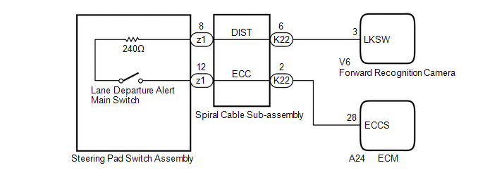
The forward recognition camera receives a lane departure alert main switch signal from the steering pad switch assembly.
WIRING DIAGRAM
CAUTION / NOTICE / HINT
NOTICE:
The vehicle is equipped with a Supplemental Restraint System (SRS) which includes components such as airbags. Before servicing (including removal or installation of parts), be sure to read the precaution for Supplemental Restraint System.
Click here
![2018 MY Camry [03/2017 - 06/2017]; SUPPLEMENTAL RESTRAINT SYSTEMS: AIRBAG SYSTEM: PRECAUTION](/t3Portal/stylegraphics/info.gif)
PROCEDURE
PROCEDURE
|
1. |
INSPECT STEERING PAD SWITCH ASSEMBLY |
(a) Remove the steering pad switch assembly.
Click here
(b) Inspect the steering pad switch assembly.
Click here
| NG |

|
|

|
2. |
INSPECT SPIRAL CABLE SUB-ASSEMBLY |
(a) Remove the spiral cable sub-assembly.
Click here
(b) Inspect the spiral cable sub-assembly.
Click here
| NG |
|
|
|
3. |
CHECK HARNESS AND CONNECTOR (SPIRAL CABLE SUB-ASSEMBLY - FORWARD RECOGNITION CAMERA) |
(a) Disconnect the K22 spiral cable sub-assembly connector.
(b) Disconnect the V6 forward recognition camera connector.
(c) Measure the resistance according to the value(s) in the table below.
Standard Resistance:
|
Tester Connection |
Condition |
Specified Condition |
|---|---|---|
|
K22-6 (DIST) - V6-3 (LKSW) |
Always |
Below 1 Ω |
|
K22-6 (DIST) or V6-3 (LKSW) - Body ground |
Always |
10 kΩ or higher |
(d) Connect the V6 forward recognition camera connector.
(e) Connect the K22 spiral cable sub-assembly connector.
| NG |
|
REPAIR OR REPLACE HARNESS OR CONNECTOR |
|
|
4. |
CHECK HARNESS AND CONNECTOR (SPIRAL CABLE SUB-ASSEMBLY - ECM) |
(a) Disconnect the K22 spiral cable sub-assembly connector.
(b) Disconnect the A24 ECM connector.
(c) Measure the resistance according to the value(s) in the table below.
Standard Resistance:
|
Tester Connection |
Condition |
Specified Condition |
|---|---|---|
|
K22-2 (ECC) - A24-28 (ECCS) |
Always |
Below 1 Ω |
|
K22-2 (ECC) or A24-28 (ECCS) - Body ground |
Always |
10 kΩ or higher |
(d) Connect the A24 ECM connector.
(e) Connect the K22 spiral cable sub-assembly connector.
| OK |
|
PROCEED TO NEXT SUSPECTED AREA SHOWN IN PROBLEM SYMPTOMS TABLE |
| NG |
|
REPAIR OR REPLACE HARNESS OR CONNECTOR |
|
|
|