
- Ignition switch ACC
- Sound is input to the microphone amplifier assembly when the user is closer than 125 mm from the microphone amplifier assembly sound holes in the roof headlining holder cover.
| Last Modified: 08-28-2024 | 6.11:8.1.0 | Doc ID: RM100000001DP4S |
| Model Year Start: 2019 | Model: Sienna | Prod Date Range: [08/2018 - ] |
| Title: AUDIO / VIDEO: AUDIO AND VISUAL SYSTEM: Microphone Circuit between Microphone and Radio Receiver; 2019 - 2020 MY Sienna [08/2018 - ] | ||
|
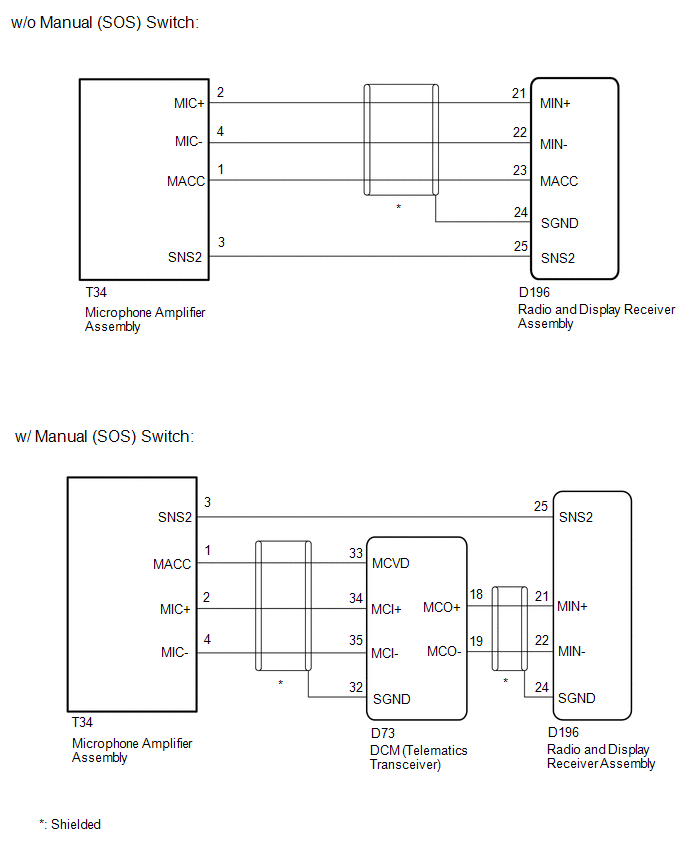
Microphone Circuit between Microphone and Radio Receiver |
DESCRIPTION
- The radio and display receiver assembly and microphone amplifier assembly are connected to each other using the microphone connection detection signal lines.
-
Using this circuit, the DCM (telematics transceiver) sends power to the microphone amplifier assembly, and the microphone amplifier assembly sends microphone signals to the radio and display receiver assembly via the DCM (telematics transceiver).*
- *: w/ Manual (SOS) Switch
WIRING DIAGRAM
CAUTION / NOTICE / HINT
NOTICE:
-
When replacing the radio receiver assembly, always replace it with a new one.
If a radio and display receiver assembly which was installed to another vehicle is used, the following may occur:
- A communication malfunction DTC may be stored.
- The radio and display receiver assembly may not operate normally.
-
Before replacing the DCM (telematics transceiver), refer to Registration.
Click here
![2018 - 2020 MY Sienna [11/2017 - ]; CELLULAR COMMUNICATION: SAFETY CONNECT SYSTEM: DCM ACTIVATION](/t3Portal/stylegraphics/info.gif)
HINT:
Depending on the parts that are replaced during vehicle inspection or maintenance, performing initialization, registration or calibration may be needed. Refer to Precaution for Audio and Visual System.(w/ Manual (SOS) Switch)
Click here
PROCEDURE
|
1. |
CHECK MICROPHONE AND VOICE RECOGNITION |
|
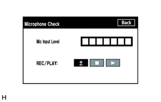
(a) Enter the "Microphone Check" screen. Refer to Check Microphone in Operation Check. Click here
|
|
(b) When voice is input into the microphone, check that the microphone input level meter changes according to the input voice.
HINT:
The microphone is active at all times when "Microphone Check" screen is displayed.
(c) Push the recording switch and perform voice recording.
HINT:
- Select the recording switch with the blower motor of the air conditioning system stopped. If an outlet of the air conditioning system is facing the microphone, noise may be recorded.
- Voice can be recorded for up to 5 seconds.
(d) Check that the recording indicator remains on while recording and that the recorded voice is played normally without noise or distortion.
OK:
All check results are normal.
| OK |

|
PROCEED TO NEXT SUSPECTED AREA SHOWN IN PROBLEM SYMPTOMS TABLE |
|
|
2. |
CHECK VEHICLE TYPE |
(a) Check the vehicle type.
|
Result |
Proceed to |
|---|---|
|
w/ Manual (SOS) Switch |
A |
|
w/o Manual (SOS) Switch |
B |
| B |
|
|
|
3. |
CHECK HARNESS AND CONNECTOR (RADIO AND DISPLAY RECEIVER ASSEMBLY - MICROPHONE AMPLIFIER ASSEMBLY) |
(a) Disconnect the D196 radio and display receiver assembly connector.
(b) Disconnect the T34 microphone amplifier assembly connector.
(c) Measure the resistance according to the value(s) in the table below.
Standard Resistance:
|
Tester Connection |
Condition |
Specified Condition |
|---|---|---|
|
D196-25 (SNS2) - T34-3 (SNS2) |
Always |
Below 1 Ω |
|
D196-25 (SNS2) - Body ground |
Always |
10 kΩ or higher |
| NG |
|
REPAIR OR REPLACE HARNESS OR CONNECTOR |
|
|
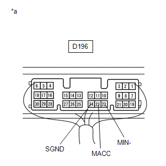
4. |
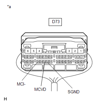
CHECK HARNESS AND CONNECTOR (RADIO AND DISPLAY RECEIVER ASSEMBLY - DCM (TELEMATICS TRANSCEIVER)) |
(a) Disconnect the D196 radio and display receiver assembly connector.
(b) Disconnect the D73 DCM (telematics transceiver) connector.
(c) Measure the resistance according to the value(s) in the table below.
Standard Resistance:
|
Tester Connection |
Condition |
Specified Condition |
|---|---|---|
|
D196-21 (MIN+) - D73-18 (MCO+) |
Always |
Below 1 Ω |
|
D196-22 (MIN-) - D73-19 (MCO-) |
Always |
Below 1 Ω |
|
D196-21 (MIN+) - Body ground |
Always |
10 kΩ or higher |
|
D196-22 (MIN-) - Body ground |
Always |
10 kΩ or higher |
|
D196-24 (SGND) - Body ground |
Always |
10 kΩ or higher |
| NG |
|
REPAIR OR REPLACE HARNESS OR CONNECTOR |
|
|
5. |
CHECK HARNESS AND CONNECTOR (DCM (TELEMATICS TRANSCEIVER) - MICROPHONE AMPLIFIER ASSEMBLY) |
(a) Disconnect the D73 DCM (telematics transceiver) connector.
(b) Disconnect the T34 microphone amplifier assembly connector.
(c) Measure the resistance according to the value(s) in the table below.
Standard Resistance:
|
Tester Connection |
Condition |
Specified Condition |
|---|---|---|
|
D73-33 (MCVD) - T34-1 (MACC) |
Always |
Below 1 Ω |
|
D73-34 (MCI+) - T34-2 (MIC+) |
Always |
Below 1 Ω |
|
D73-35 (MCI-) - T34-4 (MIC-) |
Always |
Below 1 Ω |
|
D73-33 (MCVD) - Body ground |
Always |
10 kΩ or higher |
|
D73-34 (MCI+) - Body ground |
Always |
10 kΩ or higher |
|
D73-35 (MCI-) - Body ground |
Always |
10 kΩ or higher |
|
D73-32 (SGND) - Body ground |
Always |
10 kΩ or higher |
| NG |
|
REPAIR OR REPLACE HARNESS OR CONNECTOR |
|
|
6. |
CHECK DCM (TELEMATICS TRANSCEIVER) |
|
(a) Remove the DCM (telematics transceiver) with the connector(s) still connected. |
|
(b) Measure the voltage according to the value(s) in the table below.
Standard Voltage:
|
Tester Connection |
Switch Condition |
Specified Condition |
|---|---|---|
|
D73-33 (MCVD) - Body ground |
Ignition switch ACC |
4 to 6 V |
(c) Measure the resistance according to the value(s) in the table below.
Standard Resistance:
|
Tester Connection |
Condition |
Specified Condition |
|---|---|---|
|
D73-32 (SGND) - Body ground |
Always |
Below 1 Ω |
|
D73-35 (MCI-) - Body ground |
Always |
Below 1 Ω |
| NG |
|
|
|
7. |
CHECK MICROPHONE AMPLIFIER ASSEMBLY (OUTPUT TO DCM (TELEMATICS TRANSCEIVER)) |
|
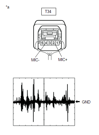
(a) Check the output waveform. (1) Remove the microphone amplifier assembly with the connector(s) still connected. Click here
(2) Connect an oscilloscope to terminal T34-2 (MIC+) and T34-4 (MIC-). (3) Turn the ignition switch ACC. (4) Sound is input to the microphone amplifier assembly when the user is closer than 125 mm from the microphone amplifier assembly sound holes in the roof headlining holder cover. (5) Check the signal waveform according to the condition(s) in the table below.
OK: The waveform is similar to that shown in the illustration. HINT: The oscilloscope waveform shown in the illustration is an example for reference only. |
|
| NG |
|
|
|
8. |
CHECK DCM (TELEMATICS TRANSCEIVER) (OUTPUT TO RADIO AND DISPLAY RECEIVER ASSEMBLY) |
|
(a) Check the output waveform. (1) Remove the DCM (telematics transceiver) with the connector(s) still connected. Click here
(2) Connect an oscilloscope to terminal D73-18 (MCO+) and D73-19 (MCO-). (3) Turn the ignition switch ACC. (4) Sound is input to the microphone amplifier assembly when the user is closer than 125 mm from the microphone amplifier assembly sound holes in the roof headlining holder cover. (5) Check the signal waveform according to the condition(s) in the table below.
OK: The waveform is similar to that shown in the illustration. HINT: The oscilloscope waveform shown in the illustration is an example for reference only. |
|
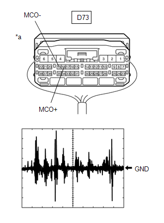
| OK |
|
| NG |
|
|
9. |
CHECK HARNESS AND CONNECTOR (RADIO AND DISPLAY RECEIVER ASSEMBLY - MICROPHONE AMPLIFIER ASSEMBLY) |
(a) Disconnect the D196 radio and display receiver assembly connector.
(b) Disconnect the T34 microphone amplifier assembly connector.
(c) Measure the resistance according to the value(s) in the table below.
Standard Resistance:
|
Tester Connection |
Condition |
Specified Condition |
|---|---|---|
|
D196-25 (SNS2) - T34-3 (SNS2) |
Always |
Below 1 Ω |
|
D196-23 (MACC) - T34-1 (MACC) |
Always |
Below 1 Ω |
|
D196-21 (MIN+) - T34-2 (MIC+) |
Always |
Below 1 Ω |
|
D196-22 (MIN-) - T34-4 (MIC-) |
Always |
Below 1 Ω |
|
D196-25 (SNS2) - Body ground |
Always |
10 kΩ or higher |
|
D196-23 (MACC) - Body ground |
Always |
10 kΩ or higher |
|
D196-21 (MIN+) - Body ground |
Always |
10 kΩ or higher |
|
D196-22 (MIN-) - Body ground |
Always |
10 kΩ or higher |
|
D196-24 (SGND) - Body ground |
Always |
10 kΩ or higher |
| NG |
|
REPAIR OR REPLACE HARNESS OR CONNECTOR |
|
|
10. |
CHECK RADIO AND DISPLAY RECEIVER ASSEMBLY |
|
(a) Remove the radio and display receiver assembly with the connector(s) still connected. |
|
(b) Measure the voltage according to the value(s) in the table below.
Standard Voltage:
|
Tester Connection |
Switch Condition |
Specified Condition |
|---|---|---|
|
D196-23 (MACC) - Body ground |
Ignition switch ACC |
4 to 6 V |
(c) Measure the resistance according to the value(s) in the table below.
Standard Resistance:
|
Tester Connection |
Condition |
Specified Condition |
|---|---|---|
|
D196-22 (MIN-) - Body ground |
Always |
Below 1 Ω |
|
D196-24 (SGND) - Body ground |
Always |
Below 1 Ω |
| NG |
|
|
|
11. |
CHECK MICROPHONE AMPLIFIER ASSEMBLY (OUTPUT TO RADIO AND DISPLAY RECEIVER ASSEMBLY) |
|
(a) Check the output waveform. (1) Remove the microphone amplifier assembly with the connector(s) still connected. Click here
(2) Connect an oscilloscope to terminal T34-2 (MIC+) and T34-4 (MIC-). (3) Turn the ignition switch ACC. (4) Sound is input to the microphone amplifier assembly when the user is closer than 125 mm from the microphone amplifier assembly sound holes in the roof headlining holder cover. (5) Check the signal waveform according to the condition(s) in the table below.
OK: The waveform is similar to that shown in the illustration. HINT: The oscilloscope waveform shown in the illustration is an example for reference only. |
|

| OK |
|
| NG |
|
|
|
|