
- EVAP pressure is below 42.11 kPa(abs) [6.11 psi(abs)] or higher than 123.761 kPa(abs) [17.95 psi(abs)]
- EVAP pressure deviates +/-10 kPa(gauge) [1.45 psi(gauge)] from actual atmosphere pressure *3
| Last Modified: 08-28-2024 | 6.11:8.1.0 | Doc ID: RM100000001DLWU |
| Model Year Start: 2019 | Model: Sienna | Prod Date Range: [08/2018 - ] |
| Title: 2GR-FKS (ENGINE CONTROL): SFI SYSTEM: EVAP System; 2019 - 2020 MY Sienna [08/2018 - ] | ||
|
EVAP System |
RELATED DTCS
|
DTC No. |
SAE |
Monitoring Item |
Link |
|---|---|---|---|
|
P00FE00 |
P00FE |
EVAP vent line blocked |
|
|
P043E00 |
P043E |
Reference orifice clogged (built into canister pump module) |
|
|
P043F00 |
P043F |
Reference orifice high-flow (built into canister pump module) |
|
|
P04417E |
P0441 |
Purge VSV stuck open |
|
|
P04417F |
P0441 |
Purge VSV (Vacuum Switching Valve) stuck closed |
|
|
P04419C |
P0441 |
Purge flow |
|
|
P045011 |
P0452 |
Canister pressure sensor (built into canister pump module) voltage low |
|
|
P045015 |
P0453 |
Canister pressure sensor (built into canister pump module) voltage high |
|
|
P04502A |
P0451 |
Canister pressure sensor (built into canister pump module) signal becomes fixed/flat |
|
|
P04502F |
P0451 |
Canister pressure sensor (built into canister pump module) signal noise |
|
|
P045500 |
P0455 |
EVAP gross leak |
|
|
P045600 |
P0456 |
EVAP small leak |
|
|
P24007E |
P2402 |
Leak detection pump stuck on (built into canister pump module) |
|
|
P24007F |
P2401 |
Leak detection pump stuck off (built into canister pump module) |
|
|
P24187E |
P2419 |
Vent valve stuck closed (built into canister pump module) |
|
|
P24187F |
P2420 |
Vent valve stuck open (vent) (built into canister pump module) |
|
|
P261029 |
P2610 |
Soak timer (built into ECM) |
|
|
P261093 |
If any EVAP system DTCs are output, the malfunctioning area can be determined using the table below.
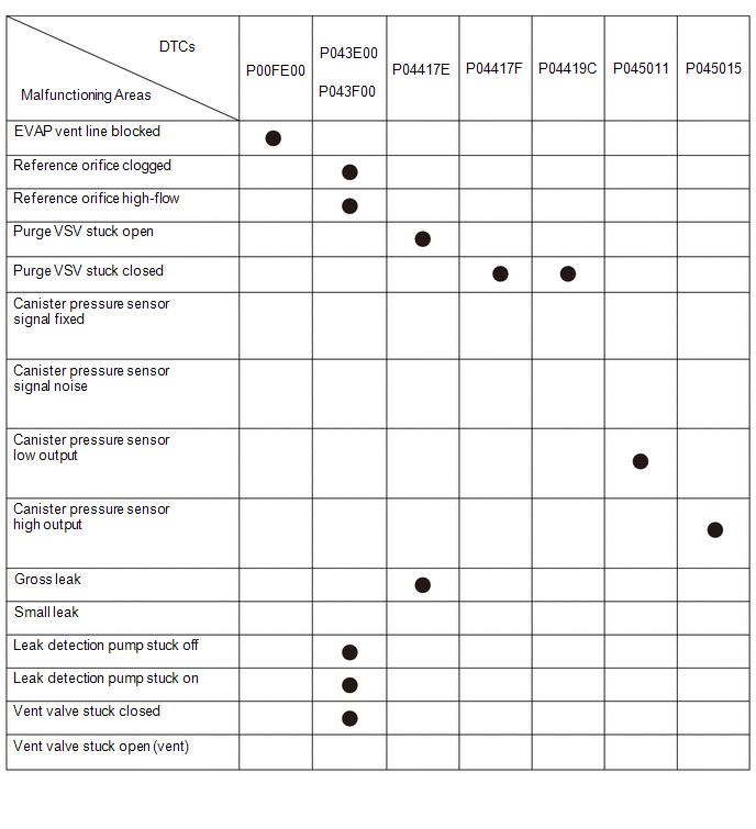
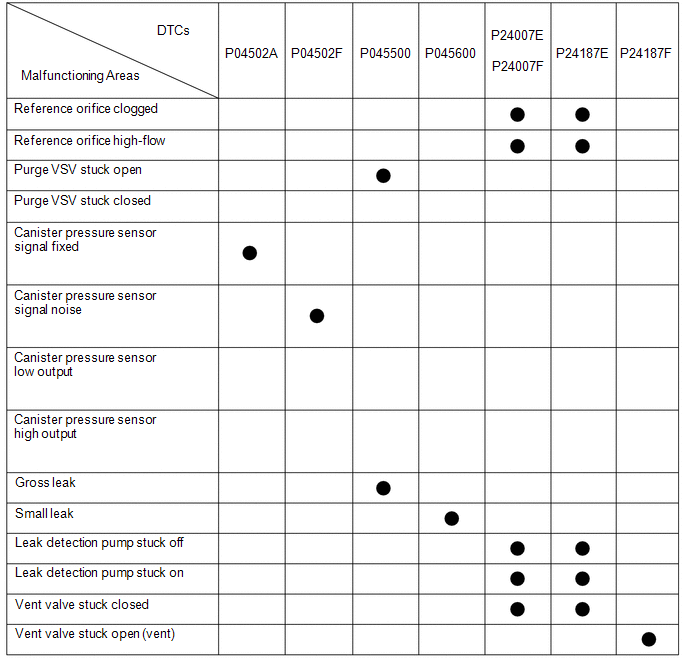
NOTICE:
If the reference pressure difference between the first and second checks is more than the specification, all the DTCs relating to the reference pressure (P043E00, P043F00, P24007E, P24007F and P24187E) will all be stored.
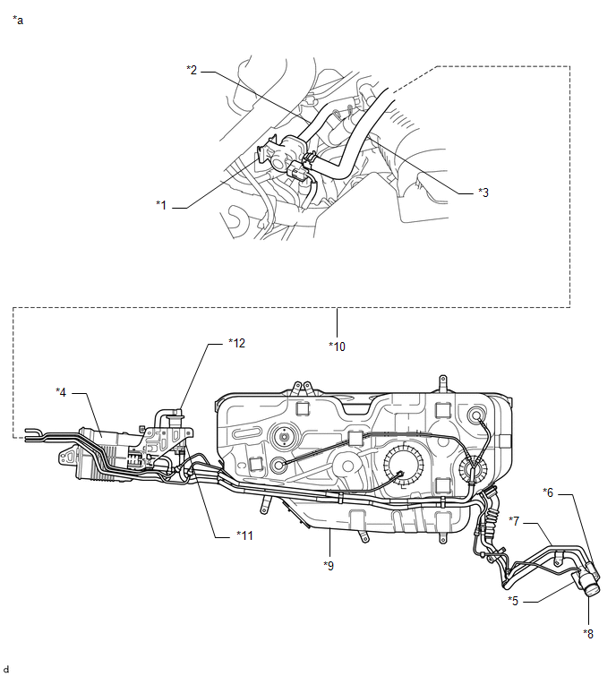
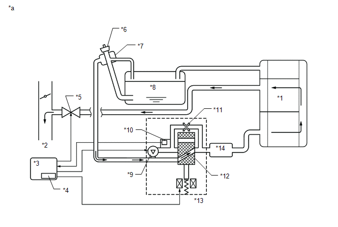
DESCRIPTION
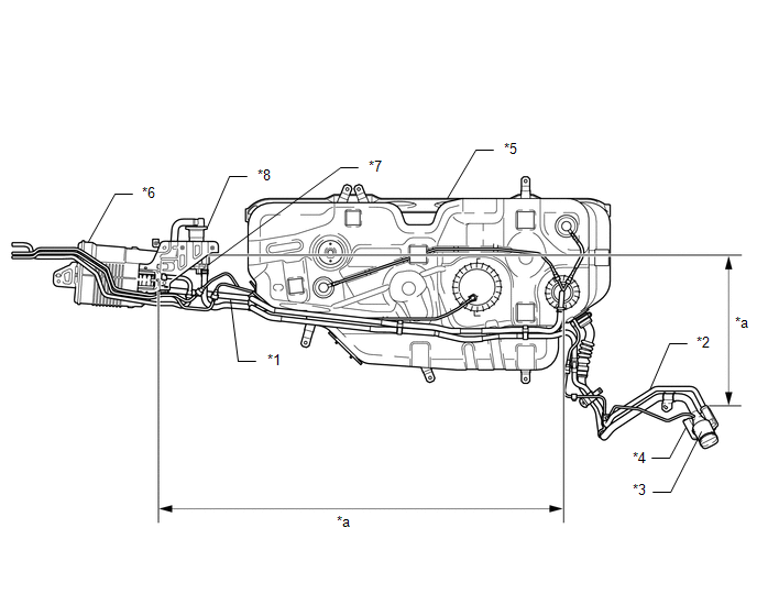
|
*1 |
Purge VSV |
*2 |
EVAP Hose (to Intake Air Surge Tank) |
|
*3 |
EVAP Hose (from Canister Assembly) |
*4 |
Canister Assembly |
|
*5 |
Canister Filter |
*6 |
Air Inlet Port (behind Fuel Tank Filler Pipe Cover) |
|
*7 |
Vent Hose |
*8 |
Fuel Cap |
|
*9 |
Fuel Tank |
*10 |
Purge Line |
|
*11 |
Canister Pump Module |
*12 |
No. 1 Charcoal Canister Filter |
|
*a |
Location of EVAP (Evaporative Emission) System |
- |
- |
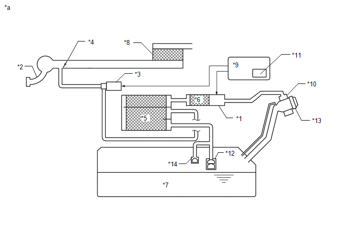
HINT:
The canister pressure sensor, the leak detection pump and the vent valve are built into the canister pump module.
|
*1 |
Canister Pump Module |
*2 |
Intake Air Surge Tank Assembly |
|
*3 |
Purge VSV |
*4 |
Throttle Valve |
|
*5 |
Canister |
*6 |
No. 1 Charcoal Canister Filter |
|
*7 |
Fuel Tank |
*8 |
Air Cleaner |
|
*9 |
ECM |
*10 |
Canister Filter |
|
*11 |
Soak Timer |
*12 |
Roll-Over Valve |
|
*13 |
Fuel Tank Cap |
*14 |
Cut-off Valve |
|
*a |
EVAP System Circuit |
- |
- |
NOTICE:
In the EVAP system of this vehicle, turning on the vent valve does not seal off the EVAP system. To check for leaks in the EVAP system, disconnect the air inlet vent hose and apply pressure from the atmospheric side of the canister.
While the engine is running, if a predetermined condition (closed-loop, etc.) is met, the purge VSV is opened by the ECM and fuel vapors stored in the canister are purged to the intake air surge tank assembly. The ECM changes the duty cycle ratio of the purge VSV to control purge flow volume.
The purge flow volume is also determined by the intake pressure. Atmospheric pressure is allowed into the canister through the vent valve to ensure that the purge flow is maintained when negative pressure (vacuum) is applied to the canister.
The following two monitors run to confirm appropriate EVAP system operation.
Key-off monitor
This monitor checks for EVAP (evaporative emission) system leaks and canister pump module malfunctions. The monitor starts 5 hours* after the ignition switch is turned off. At least 5 hours are required for the fuel to cool down to stabilize the EVAP pressure, thus making the EVAP system monitor more accurate.
The leak detection pump creates negative pressure (vacuum) in the EVAP system and the pressure is measured. Finally, the ECM monitors for leaks from the EVAP system, and malfunctions in both the canister pump module and purge VSV based on the EVAP pressure.
HINT:
*: If the engine coolant temperature is not less than 35°C (95°F) 5 hours after the ignition switch is turned off, the monitor check starts 2 hours later. If it is still not less than 35°C (95°F) 7 hours after the ignition switch is turned off, the monitor check starts 2.5 hours later.
Purge flow monitor
The purge flow monitor consists of the 2 monitors. The 1st monitor is conducted every time and the 2nd monitor is activated if necessary.
-
The 1st monitor
While the engine is running and the purge VSV (Vacuum Switching Valve) is on (open), the ECM monitors the purge flow by measuring the EVAP pressure change. If negative pressure is not created, the ECM begins the 2nd monitor.
-
The 2nd monitor
The vent valve is turned on (closed) and the EVAP pressure is then measured. If the variation in the pressure is less than 0.15 kPa(gauge) [1.125 mmHg(gauge)], the ECM interprets this as the purge VSV being stuck closed, illuminates the MIL and stores DTC P0441 (2 trip detection logic).
-
Atmospheric pressure check:
- In order to ensure reliable malfunction detection, the variation between the atmospheric pressures, before and after of the purge flow monitor, is measured by the ECM.
|
*1 |
Canister |
*2 |
to Intake Air Surge Tank Assembly |
|
*3 |
ECM |
*4 |
Soak Timer |
|
*5 |
Purge VSV (on) |
*6 |
Fuel Tank Cap |
|
*7 |
Canister Filter |
*8 |
Fuel Tank |
|
*9 |
Leak Detection Pump (Off) |
*10 |
Canister Pressure Sensor |
|
*11 |
Reference Orifice (0.02 inches) |
*12 |
Vent Valve (Off) |
|
*13 |
Canister Pump Module |
*14 |
No. 1 Charcoal Canister Filter |
|
*a |
EVAP Purge Flow |
- |
- |
|
Component |
Operation |
|---|---|
|
Canister |
Contains activated charcoal to absorb EVAP (Evaporative Emissions) generated in fuel tank. |
|
Cut-off valve |
Located in fuel tank. Valve floats and closes when fuel tank is 100% full. |
|
Purge VSV (Vacuum Switching Valve) |
Opens or closes line between canister and intake air surge tank assembly. ECM uses purge VSV to control EVAP purge flow. In order to discharge EVAP absorbed by canister to intake air surge tank assembly, ECM opens purge VSV. EVAP discharge volume to intake air surge tank assembly controlled by purge VSV duty cycle (current-carrying time). (Open: on, Close: off) |
|
Roll-over valve |
Located in fuel tank. Valve closes by its own weight when vehicle overturns to prevent fuel from spilling out. |
|
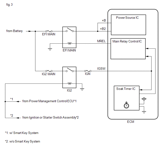
Soak timer |
Built into ECM. To ensure accurate EVAP monitor, measures 5 hours (+/-15 min) after ignition switch is turned off. This allows fuel to cool down, stabilizing EVAP pressure. When approximately 5 hours elapsed, ECM activates (refer to fig. 3). |
|
Canister pump module |
Consists of (a) to (d) below. Canister pump module cannot be disassembled. |
|
(a) Vent valve |
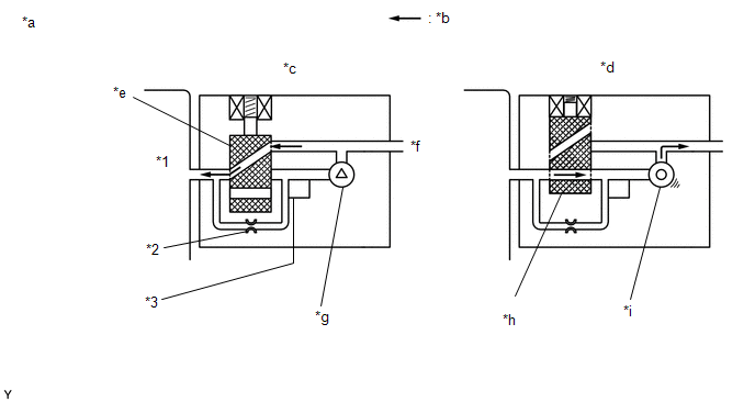
Vents and closes EVAP system. When ECM turns valve on, EVAP system is closed. When ECM turns valve off, EVAP system is vented. Negative pressure (vacuum) is created in EVAP system to check for EVAP leaks by closing purge VSV, turning on vent valve (closing it) and operating leak detection pump (refer to fig. 1). |
|
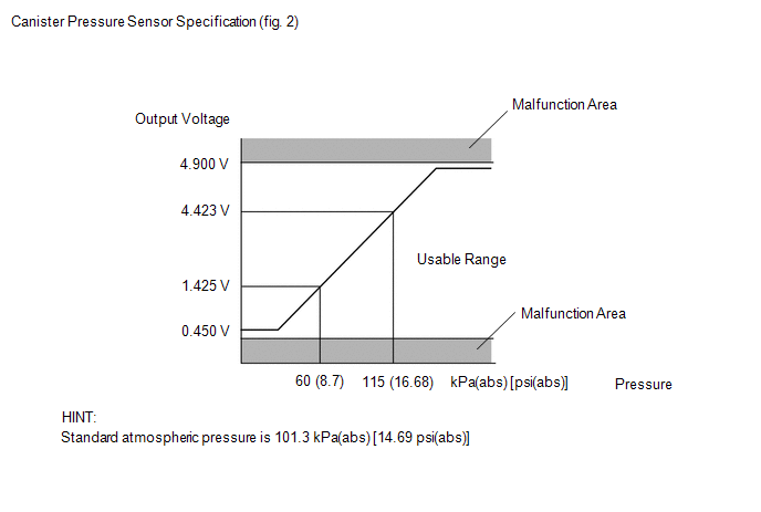
(b) Canister pressure sensor |
Indicates pressure as voltages. ECM supplies regulated 5 V to pressure sensor, and uses feedback from sensor to monitor EVAP system pressure (refer to fig. 2). |
|
(c) Leak detection pump |
Creates negative pressure (vacuum) in EVAP system for leak check. |
|
(d) Reference orifice |
Has opening with 0.02 inch diameter. Vacuum is produced through orifice by closing purge VSV, turning off vent valve and operating leak detection pump, to monitor reference pressure. Reference pressure is used when checking for small EVAP leaks. |
|
*1 |
Canister |
*2 |
Reference Orifice (0.02 Inch) |
|
*3 |
Canister Pressure Sensor |
- |
- |
|
*a |
Canister Pump Module (fig. 1) |
*b |
Airflow |
|
*c |
Condition: Purge Flow |
*d |
Condition: Leak Check |
|
*e |
Vent Valve: off (vent) |
*f |
to Canister Filter (Atmosphere) |
|
*g |
Leak Detection Pump: off |
*h |
Vent Valve: on (closed) |
|
*i |
Leak Detection Pump: on |
- |
- |
WIRING DIAGRAM
Refer to DTC P045011.
Click here
![2018 - 2020 MY Sienna [11/2017 - ]; 2GR-FKS (ENGINE CONTROL): SFI SYSTEM: P045011,P045015,P04502A,P04502F; Evaporative Emission System Pressure Sensor/Switch Circuit Short to Ground](/t3Portal/stylegraphics/info.gif)
CAUTION / NOTICE / HINT
NOTICE:
- Inspect the fuses for circuits related to this system before performing the following procedure.
- The Techstream is required to conduct the following diagnostic troubleshooting procedure.
HINT:
- Using the Techstream monitor results enables the EVAP (Evaporative Emission) system to be confirmed.
- Read freeze frame data using the Techstream. The ECM records vehicle and driving condition information as freeze frame data the moment a DTC is stored. When troubleshooting, freeze frame data can help determine if the vehicle was moving or stationary, if the engine was warmed up or not, if the air fuel ratio was lean or rich, and other data from the time the malfunction occurred.
CONFIRMATION DRIVING PATTERN
HINT:
After a repair, check Monitor Status by performing the Key-Off Monitor Confirmation and Purge Flow Monitor Confirmation described below.
KEY-OFF MONITOR CONFIRMATION
(a) Preconditions
The monitor will not run unless:
- The vehicle has been driven for 10 minutes or more (in a city area or on a freeway).
- The fuel tank is less than 90% full.
- The altitude is less than 2400 m (7875 ft.).
- The engine coolant temperature is between 4.4 and 35°C (40 and 95°F).
- The intake air temperature is between 4.4 and 35°C (40 and 95°F).
- The vehicle remains stationary (the vehicle speed is 0 km/h [0 mph]).
(b) Monitor Conditions
- Allow the engine to idle for at least 5 minutes.
-
Turn the ignition switch off and wait for 6 hours (8 or 10.5 hours).
HINT:
Do not start the engine until checking Monitor Status. If the engine is started, the steps described above must be repeated.
(c) Monitor Status
- Connect the Techstream to the DLC3.
- Turn the ignition switch to ON.
- Turn the Techstream on.
- Enter the following menus: Powertrain / Engine / Monitor / Current Monitor.
-
Check the Monitor Status displayed on the Techstream.
HINT:
If Incomplete is displayed, the monitor did not complete. Make sure that the preconditions have been met, and perform the Monitor Conditions again.
PURGE FLOW MONITOR CONFIRMATION (P04419C)
HINT:
Perform this monitor confirmation after the Key-Off Monitor Confirmation shows Complete.
(a) Preconditions
The monitor will not run unless:
- The vehicle has been driven for 10 minutes or more (in a city area or on a freeway).
- The engine coolant temperature is 4.4°C (40°F) or higher.
- The intake air temperature is 4.4°C (40°F) or higher.
(b) Monitor Conditions
- Release the pressure from the fuel tank by removing and reinstalling the fuel cap.
- Warm the engine up until the engine coolant temperature reaches higher than 75°C (167°F).
- Increase the engine speed to 3000 rpm once.
- Allow the engine to idle and turn the A/C switch on for 1 minute.
(c) Monitor Status
- Turn the ignition switch off (if ON or if the engine is running).
- Connect the Techstream to the DLC3.
- Turn the ignition switch to ON.
- Turn the Techstream on.
- Enter the following menus: Powertrain / Engine / Monitor / Current Monitor.
-
Check the Monitor Status displayed on the Techstream.
HINT:
If Incomplete is displayed, the monitor did not complete. Make sure that the preconditions have been met, and perform the Monitor Conditions again.
MONITOR RESULT
Refer to detailed information in Checking Monitor Status.
Click here
P0456: Evaporative System / SMALL LEAK
|
Monitor ID |
Test ID |
Scaling |
Unit |
Description |
|---|---|---|---|---|
|
$3D |
$C9 |
Multiply by 0.001 |
kPa |
Test value for small leak (P0456) |
P0455: Evaporative System / GROSS LEAK
|
Monitor ID |
Test ID |
Scaling |
Unit |
Description |
|---|---|---|---|---|
|
$3D |
$CA |
Multiply by 0.001 |
kPa |
Test value for gross leak (P0455) |
P2401: Evaporative System / VACUUM PMP OFF
|
Monitor ID |
Test ID |
Scaling |
Unit |
Description |
|---|---|---|---|---|
|
$3D |
$CB |
Multiply by 0.001 |
kPa |
Test value for leak detection pump OFF stuck (P2401) |
P2402: Evaporative System / VACUUM PMP ON
|
Monitor ID |
Test ID |
Scaling |
Unit |
Description |
|---|---|---|---|---|
|
$3D |
$CD |
Multiply by 0.001 |
kPa |
Test value for leak detection pump ON stuck (P2402) |
P2420: Evaporative System / VENT VALVE OFF
|
Monitor ID |
Test ID |
Scaling |
Unit |
Description |
|---|---|---|---|---|
|
$3D |
$CE |
Multiply by 0.001 |
kPa |
Test value for vent valve OFF stuck (P2420) |
P2419: Evaporative System / VENT VALVE ON
|
Monitor ID |
Test ID |
Scaling |
Unit |
Description |
|---|---|---|---|---|
|
$3D |
$CF |
Multiply by 0.001 |
kPa |
Test value for vent valve ON stuck (P2419) |
P043E: Evaporative System / ORIFICE CLOGGED
|
Monitor ID |
Test ID |
Scaling |
Unit |
Description |
|---|---|---|---|---|
|
$3D |
$D0 |
Multiply by 0.001 |
kPa |
Test value for reference orifice low flow (P043E) |
P043F: Evaporative System / ORIFICE HI-FLW
|
Monitor ID |
Test ID |
Scaling |
Unit |
Description |
|---|---|---|---|---|
|
$3D |
$D1 |
Multiply by 0.001 |
kPa |
Test value for reference orifice high flow (P043F) |
P0441: Evaporative System / PURGE VSV CLOSED
|
Monitor ID |
Test ID |
Scaling |
Unit |
Description |
|---|---|---|---|---|
|
$3D |
$D4 |
Multiply by 0.001 |
kPa |
Test value for purge VSV close stuck (P0441) |
P0441: Evaporative System / PURGE VSV OPENED
|
Monitor ID |
Test ID |
Scaling |
Unit |
Description |
|---|---|---|---|---|
|
$3D |
$D5 |
Multiply by 0.001 |
kPa |
Test value for purge VSV open stuck (P0441) |
P0441: Evaporative System / PURGE FLOW
|
Monitor ID |
Test ID |
Scaling |
Unit |
Description |
|---|---|---|---|---|
|
$3D |
$D7 |
Multiply by 0.001 |
kPa |
Test value for purge flow insufficient (P0441) |
PROCEDURE
|
1. |
CONFIRM DTC |
(a) Turn the ignition switch off and wait for 10 seconds.
(b) Turn the ignition switch to ON.
(c) Turn the ignition switch off and wait for 10 seconds.
(d) Connect the Techstream to the DLC3.
(e) Turn the ignition switch to ON.
(f) Turn the Techstream on.
(g) Enter the following menus: Powertrain / Engine / Trouble Codes.
(h) Confirm the DTCs and freeze frame data.
If any EVAP system DTCs are stored, the malfunctioning area can be determined using the table below.
NOTICE:
If the reference pressure difference between the first and second checks is greater than the specification, all the DTCs relating to the reference pressure (P043E00, P043F00, P24007E, P24007F and P24187E) are stored.
|
|
2. |
PERFORM EVAP SYSTEM CHECK (AUTOMATIC MODE) |
NOTICE:
- The Evaporative System Check (Automatic Mode) consists of 6 steps performed automatically by the Techstream. It takes a maximum of approximately 24 minutes.
- Do not perform the Evaporative System Check when the fuel tank is more than 85% full because the cut-off valve may be closed, making the fuel tank leak check unavailable.
- Do not run the engine during this operation.
- When the temperature of the fuel is 35°C (95°F) or higher, a large amount of vapor forms and any check results become inaccurate. When performing the Evaporative System Check, keep the temperature less than 35°C (95°F).
(a) Connect the Techstream to the DLC3.
(b) Turn the ignition switch to ON.
(c) Turn the Techstream on.
(d) Clear the DTCs.
(e) Turn the ignition switch off and wait for at least 30 seconds.
(f) Turn the ignition switch to ON and turn the Techstream on.
(g) Enter the following menus: Powertrain / Engine / Utility / Evaporative System Check / Automatic Mode.
(h) After the Evaporative System Check is completed, check for pending DTCs by entering the following menus: Powertrain / Engine / Trouble Codes.
HINT:
If no pending DTCs are displayed, perform the Confirmation Driving Pattern. After this confirmation, check for pending DTCs. If no DTCs are displayed, the EVAP system is normal.
|
|
3. |
PERFORM EVAP SYSTEM CHECK (MANUAL MODE) |
NOTICE:
- In the Evaporative System Check (Manual Mode), the series of 6 Evaporative System Check steps are performed manually using the Techstream.
- Do not perform the Evaporative System Check when the fuel tank is more than 90% full because the cut-off valve may be closed, making the fuel tank leak check unavailable.
- Do not run the engine during this operation.
- When the temperature of the fuel is 35°C (95°F) or higher, a large amount of vapor forms and any check results become inaccurate. When performing the Evaporative System Check, keep the temperature less than 35°C (95°F).
(a) Connect the Techstream to the DLC3.
(b) Turn the ignition switch to ON.
(c) Turn the Techstream on.
(d) Clear the DTCs.
Click here
(e) Turn the ignition switch off and wait for at least 30 seconds.
(f) Turn the ignition switch to ON and turn the Techstream on.
(g) Enter the following menus: Powertrain / Engine / Utility / Evaporative System Check / Manual Mode.
|
|
4. |
PERFORM EVAP SYSTEM CHECK (STEP 1/6) |
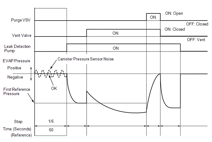
(a) Check the EVAP pressure in step 1/6.
|
DTC*1 |
Result |
Suspected Trouble Area |
Proceed to |
|---|---|---|---|
|
- |
Virtually no variation in EVAP pressure |
Not yet determined |
A |
|
P04502F |
EVAP pressure fluctuates by +/-0.3 kPa(gauge) [0.044 psi(gauge)] or higher |
Canister pressure sensor signal noise |
B |
|
(P045011 or P045015)*2 |
|
Canister pressure sensor or its circuit has malfunction |
C |
- *1: These DTCs are already present in the ECM when the vehicle arrives and are confirmed in the "Confirm DTC" procedure above.
- *2: If the canister pressure sensor circuit has an open or short, DTC P045011 or P045015 is stored 0.5 seconds after the ignition switch is turned ON.
HINT:
*3: Canister pressure sensor standard output range is 70 to 110 kPa(abs) [10.15 to 15.95 psi(abs)]. This varies by weather.
| B |

|
| C |
|
|
|
5. |
PERFORM EVAP SYSTEM CHECK (STEP 1/6 TO 2/6) |
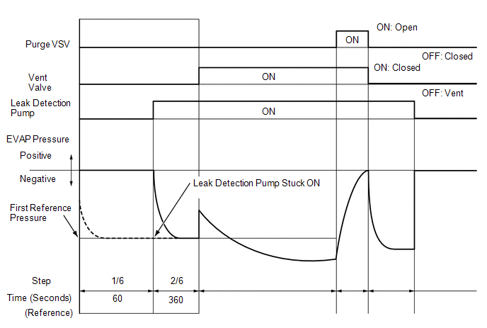
(a) Check the EVAP pressure in steps 1/6 and 2/6.
|
DTC* |
Result |
Suspected Trouble Area |
Proceed to |
|---|---|---|---|
|
- |
Virtually no variation in EVAP pressure during step 1/6. Then decreases to reference pressure |
Not yet determined |
A |
|
P24007E |
Small difference between EVAP pressures during steps 1/6 and 2/6 |
Leak detection pump stuck ON |
B |
- *: These DTCs are already present in the ECM when the vehicle arrives and are confirmed in the "Confirm DTC" procedure above.
HINT:
The first reference pressure is the value determined in step 2/6.
| B |
|
|
|
6. |
PERFORM EVAP SYSTEM CHECK (STEP 2/6) |
HINT:
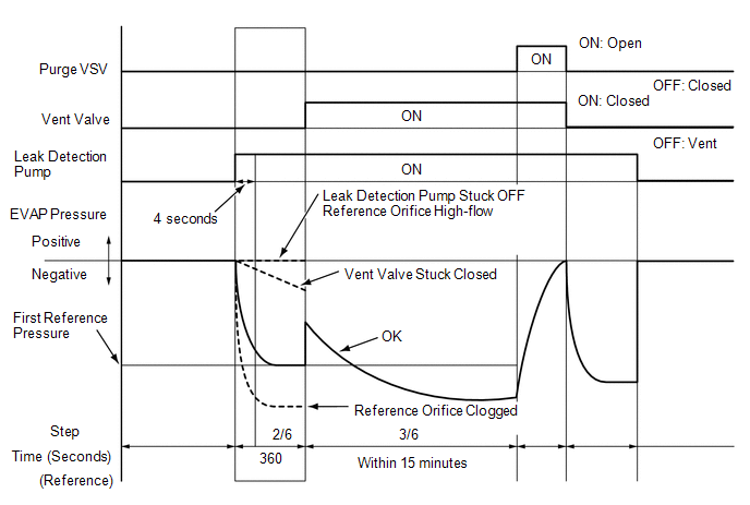
Make a note of the pressures checked in inspection items (A) and (B) below.
(a) Check the EVAP pressure 4 seconds after the leak detection pump is activated*1 (A).
*1: The leak detection pump begins to operate as step 1/6 finishes and step 2/6 starts.
(b) Check the EVAP pressure again when it has stabilized. This pressure is the reference pressure (B).
|
DTC*2. |
Result |
Suspected Trouble Area |
Proceed to |
|---|---|---|---|
|
- |
EVAP pressure in inspection item (B) is between -4.85 kPa(gauge) and -1.057 kPa(gauge) [-0.703 psi(gauge) and -0.153 psi(gauge)] |
Not yet determined |
A |
|
P043F00 and P24007F |
EVAP pressure in inspection item (B) is -1.057 kPa(gauge) [-0.153 psi(gauge)] or higher |
|
B |
|
P043E00 |
EVAP pressure in inspection item (B) is less than -4.85 kPa(gauge) [-0.703 psi(gauge)] |
Reference orifice clogged |
C |
|
P24187E |
EVAP pressure in inspection item (A) is higher than -0.25 kPa(gauge) [-0.036 psi(gauge)] |
|
D |
- *2: These DTCs are already present in the ECM when the vehicle arrives and are confirmed in the "Confirm DTC" procedure above.
| B |
|
| C |
|
| D |
|
|
|
7. |
PERFORM EVAP SYSTEM CHECK (STEP 2/6 TO 3/6) |
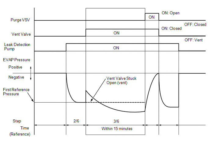
(a) Check the EVAP pressure in step 3/6.
|
DTC* |
Result |
Suspected Trouble Area |
Proceed to |
|---|---|---|---|
|
- |
EVAP pressure increases by 0.3 kPa(gauge) [0.044 psi(gauge)] or higher within 10 seconds of proceeding from step 2/6 to step 3/6 |
Not yet determined |
A |
|
P24187F |
No variation in EVAP pressure even after proceeding from step 2/6 to step 3/6 |
|
B |
|
P04502A |
No variation in EVAP pressure during steps 1/6 through 3/6 |
|
C |
- *: These DTCs are already present in the ECM when the vehicle arrives and are confirmed in the "Confirm DTC" procedure above.
| B |
|
| C |
|
|
|
8. |
PERFORM EVAP SYSTEM CHECK (STEP 3/6) |
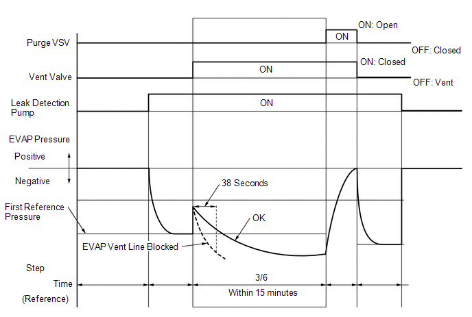
(a) Check the EVAP pressure in step 3/6.
|
DTC* |
Result |
Suspected Trouble Area |
Proceed to |
|---|---|---|---|
|
- |
Other than below |
Not yet determined |
A |
|
P00FE00 |
Within 38 seconds after step 3/6 begins, the EVAP pressure becomes less than -3.96 kPa(gauge) (-0.57 psi(gauge)) HINT: Vary with first reference pressure. |
|
B |
- *: These DTCs are already present in the ECM when the vehicle arrives and are confirmed in the "Confirm DTC" procedure above.
HINT:
A few minutes are required for the EVAP pressure to become saturated. When there is little fuel in the fuel tank, it takes up to 15 minutes.
| B |
|
|
|
9. |
PERFORM EVAP SYSTEM CHECK (STEP 4/6) |
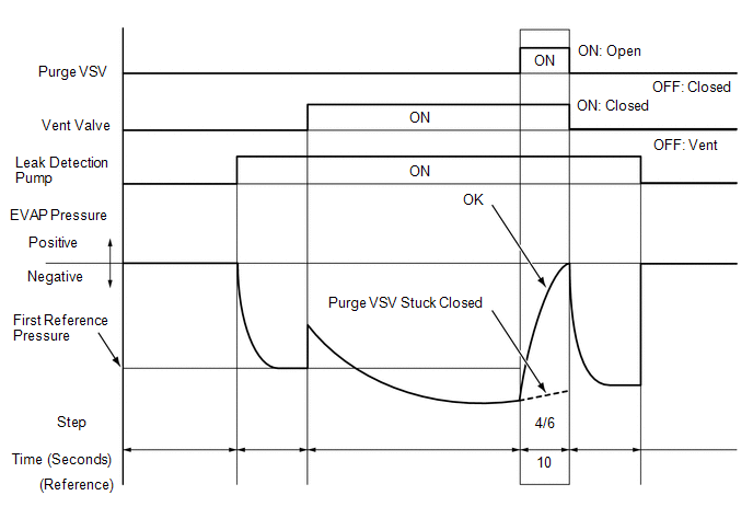
(a) Check the EVAP pressure in step 4/6.
|
DTC*1 |
Result |
Suspected Trouble Area |
Proceed to |
|---|---|---|---|
|
- |
EVAP pressure increases by 0.3 kPa(gauge) [0.044 psi(gauge)] or higher within 10 seconds of proceeding from step 3/6 to step 4/6 |
Not yet determined |
A |
|
P04419C*2 |
EVAP pressure increases by 0.3 kPa(gauge) [0.044 psi(gauge)] or higher within 10 seconds of proceeding from step 3/6 to step 4/6 |
|
B |
|
P04417F |
Variation in EVAP pressure is less than 0.3 kPa(gauge) [0.044 psi(gauge)] for 10 seconds, after proceeding from step 3/6 to step 4/6 |
|
C |
- *1: These DTCs are already present in the ECM when the vehicle arrives and are confirmed in the "Confirm DTC" procedure above.
- *2: This result suggests that due to purge line blockage or purge VSV malfunction, the DTC was stored by the purge flow monitor while the engine was running, or that key-off monitor test result were nearly borderline values.
| B |
|
| C |
|
|
|
10. |
PERFORM EVAP SYSTEM CHECK (STEP 5/6) |
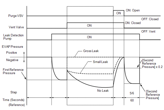
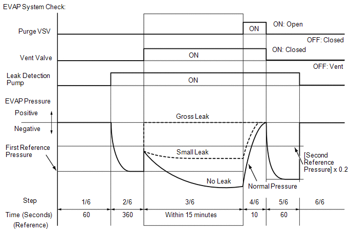
(a) Check the EVAP pressure in step 5/6.
(b) Compare the EVAP pressure in step 3/6 and the second reference pressure (step 5/6).
|
DTC* |
Result |
Suspected Trouble Area |
Proceed to |
|---|---|---|---|
|
- |
EVAP pressure from step 3/6 lower than second reference pressure (step 5/6) |
Not yet determined (no leakage from EVAP system) |
A |
|
P04417E and P045500 |
EVAP pressure from step 3/6 higher than [second reference pressure (step 5/6) x 0.2] |
|
B |
|
P045600 |
EVAP pressure from step 3/6 higher than second reference pressure (step 5/6) |
EVAP small leak |
- *: These DTCs are already present in the ECM when the vehicle arrives and are confirmed in the "Confirm DTC" procedure above.
| B |
|
|
|
11. |
REPAIR OR REPLACE PARTS AND COMPONENTS INDICATED BY OUTPUT DTCS |
(a) Repair the malfunctioning areas indicated by the DTCs that had been confirmed when the vehicle was brought in.
| NEXT |
|
|
12. |
INSPECT EVAP HOSE (PURGE VSV - CANISTER) |
(a) Check for blockages in the EVAP purge line between the purge VSV and canister.
OK:
No blockages in the EVAP purge line between the purge VSV and canister.
| OK |
|
| NG |
|
|
13. |
PERFORM ACTIVE TEST USING TECHSTREAM (PURGE VSV) |
|
*1 |
Purge VSV |
|
*2 |
Fuel Vapor Feed Hose (to Canister) |
(a) Enter the following menus: Powertrain / Engine / Active Test / Activate the EVAP Purge VSV.
(b) Disconnect the fuel vapor feed hose (connected to the canister) from the purge VSV.
(c) Start the engine.
(d) Using the Techstream, turn off the purge VSV (Activate the VSV for Evap Control: OFF).
(e) Use your finger to confirm that the purge VSV has no suction.
(f) Using the Techstream, turn on the purge VSV (Activate the VSV for Evap Control: ON).
(g) Use your finger to confirm that the purge VSV has suction.
|
Test Result |
Suspected Trouble Area |
Proceed to |
|---|---|---|
|
No suction when purge VSV turned off, and suction applied when turned on |
Blockage in the purge line is considered (based on result of step 9):
|
A |
|
Leakage is considered (based on result of step 10):
|
B |
|
|
Suction applied when purge VSV turned off |
|
C |
|
No suction when purge VSV turned on |
|
D |
| B |
|
| C |
|
| D |
|
|
|
14. |
INSPECT EVAP HOSE (PURGE VSV - CANISTER) |
(a) Check for blockages in the EVAP purge line between the purge VSV and canister.
OK:
No blockages in the EVAP purge line between the purge VSV and canister.
| NG |
|
|
|
15. |
INSPECT CANISTER (CHARCOAL FILTER INSIDE CANISTER) |
(a) Check for filter blockage in the canister.
Click here
OK:
No blockages in the canister.
| NG |
|
|
|
16. |
INSPECT NO. 1 CHARCOAL CANISTER FILTER (CANISTER ASSEMBLY) |
(a) Check for filter blockage in the No. 1 charcoal canister filter (Canister assembly).
Click here
OK:
No blockages in the No. 1 charcoal canister filter (Canister assembly).
| OK |
|
| NG |
|
|
17. |
REPAIR OR REPLACE EVAP PURGE LINE (PURGE VSV - CANISTER) |
| NEXT |
|
|
18. |
CHECK FUEL TANK CAP ASSEMBLY |
(a) Check that the fuel tank cap is correctly installed and confirm that the fuel tank cap meets OEM specifications.
(b) Tighten the fuel tank cap firmly (only one click sound could be heard).
HINT:
If an EVAP tester is available, check the fuel tank cap using the tester.
(1) Remove the fuel tank cap and install it onto a fuel tank cap adapter.
(2) Connect an EVAP tester pump hose to the adapter, and pressurize the cap to 3.2 to 3.7 kPa(gauge) [0.464 to 0.537 psi(gauge)] using an EVAP tester pump.
(3) Seal the adapter and wait for 2 minutes.
(4) Check the pressure. If the pressure is 2 kPa(gauge) [0.29 psi(gauge)] or higher, the fuel tank cap is normal.
|
Test Result |
Suspected Trouble Area |
Proceed to |
|---|---|---|
|
Fuel tank cap correctly installed |
- |
A |
|
Fuel tank cap loose |
|
B |
|
Defective fuel tank cap |
- |
|
|
No fuel tank cap |
- |
C |
| B |
|
| C |
|
|
|
19. |
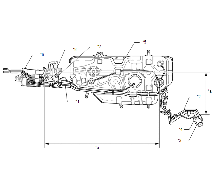
LOCATE EVAP LEAK PART |
(a) Disconnect the vent hose.
|
*1 |
Fuel Tank Vent Hose |
*2 |
Vent Hose |
|
*3 |
Air Inlet Port (behind Fuel Tank Filler Pipe Cover) |
*4 |
Canister Filter |
|
*5 |
Fuel Tank |
*6 |
Canister Assembly |
|
*7 |
Canister Pump Module |
*8 |
No. 1 Charcoal Canister Filter |
|
*a |
Inspection Area (Check for disconnection and/or cracks) |
- |
- |
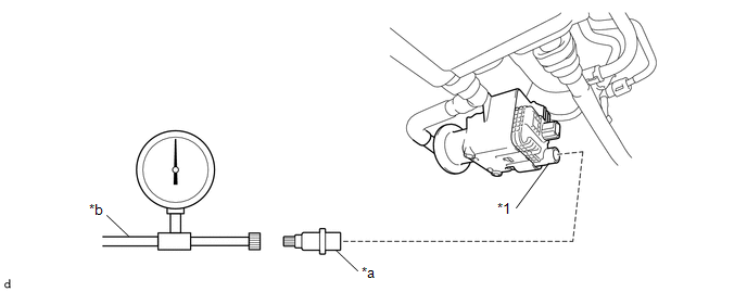
(b) Connect the EVAP pressure tester tool to the canister pump module with the adapter.
|
*1 |
Canister Pump Module |
- |
- |
|
*a |
Adapter |
*b |
EVAP Pressure Tester Tool |
(c) Pressurize the EVAP system to 3.2 to 3.7 kPa(gauge) [0.46 to 0.54 psi(gauge)].
(d) Apply soapy water to the piping and connecting parts of the EVAP system.
(e) Look for areas where bubbles appear. This indicates the leak point.
(f) Repair or replace the leak point.
HINT:
Disconnect the hose between the canister and fuel tank from the canister. Block the canister side and conduct an inspection. In this way, the fuel tank can be excluded as an area suspected of causing fuel leaks.
| NEXT |
|
|
20. |
CORRECTLY REINSTALL OR REPLACE FUEL TANK CAP ASSEMBLY |
HINT:
- When reinstalling the fuel tank cap, tighten it firmly (only one click sound could be heard).
- When replacing the fuel tank cap, use a fuel tank cap that meets OEM specifications, and install it firmly.
| NEXT |
|
|
21. |
REPLACE FUEL TANK CAP ASSEMBLY |
HINT:
When installing the fuel tank cap, tighten it firmly (only one click sound could be heard).
| NEXT |
|
|
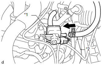
22. |
INSPECT PURGE VSV |
|
*1 |
Fuel Vapor Feed Hose (to Canister) |
|
*2 |
Purge VSV |
(a) Turn the ignition switch off.
(b) Disconnect the purge VSV connector.
(c) Disconnect the fuel vapor feed hose (connected to the canister) from the purge VSV.
(d) Start the engine.
(e) Use your finger to confirm that the purge VSV has no suction.
|
Test Result |
Suspected Trouble Area |
Proceed to |
|---|---|---|
|
No suction |
|
A |
|
Suction applied |
Purge VSV |
B |
| A |
|
| B |
|
|
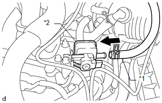
23. |
CHECK EVAP HOSE (PURGE VSV - INTAKE AIR SURGE TANK ASSEMBLY) |
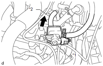
|
*1 |
Purge VSV |
|
*2 |
Fuel Vapor Feed Hose (to Intake Air Surge Tank Assembly) |
(a) Disconnect the fuel vapor feed hose (connected to the intake air surge tank assembly) from the purge VSV.
(b) Start the engine.
(c) Use your finger to confirm that the hose has suction.
|
Test Result |
Suspected Trouble Area |
Proceed to |
|---|---|---|
|
Suction applied |
EVAP hose between purge VSV and intake air surge tank assembly normal
|
A |
|
No suction |
|
B |
| B |
|
|
|
24. |
INSPECT PURGE VSV |
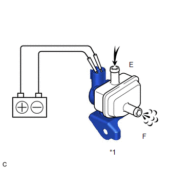
|
*1 |
Purge VSV |
(a) Remove the purge VSV.
(b) Apply battery voltage to the terminals of the purge VSV.
(c) Confirm that air flows from port E to port F.
|
Test Result |
Condition |
Suspected Trouble Area |
Proceed to |
|---|---|---|---|
|
Air flows |
Battery voltage is applied to purge VSV terminals |
Purge VSV normal
|
A |
|
No air flow |
Battery voltage is applied to purge VSV terminals |
Purge VSV |
B |
| B |
|
|
|
25. |
CHECK TERMINAL VOLTAGE (POWER SOURCE OF PURGE VSV) |
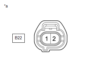
|
*a |
Front view of wire harness connector (to Purge VSV) |
(a) Disconnect the purge VSV connector.
(b) Turn the ignition switch to ON.
(c) Measure the voltage according to the value(s) in the table below.
|
Tester Connection |
Switch Condition |
Specified Condition |
Suspected Trouble Area |
Proceed to |
|---|---|---|---|---|
|
B22-1 - Body ground |
Ignition switch ON |
11 to 14 V |
Purge VSV power source normal
|
A |
|
Other than result above |
Wire harness or connectors between purge VSV and battery |
B |
| B |
|
REPAIR OR REPLACE HARNESS OR CONNECTOR |
|
|
26. |
CHECK HARNESS AND CONNECTOR (PURGE VSV - ECM) |
(a) Disconnect the B22 purge VSV connector.
(b) Disconnect the B67 ECM connector.
(c) Measure the resistance according to the value(s) in the table below.
Standard Resistance:
|
Tester Connection |
Condition |
Specified Condition |
|---|---|---|
|
B22-2 - B67-65 (PRG) |
Always |
Below 1 Ω |
|
B22-2 or B67-65 (PRG) - Body ground |
Always |
10 kΩ or higher |
| OK |
|
| NG |
|
|
27. |
REPLACE PURGE VSV |
(a) Replace the purge VSV.
Click here
| NEXT |
|
|
28. |
INSPECT INTAKE AIR SURGE TANK ASSEMBLY (EVAP PURGE PORT) |
(a) Stop the engine.
(b) Disconnect the EVAP hose from the intake air surge tank assembly.
(c) Start the engine.
(d) Use your finger to confirm that the port of the intake air surge tank assembly has suction.
|
Tester Connection |
Suspected Trouble Area |
Proceed to |
|---|---|---|
|
Suction applied |
EVAP hose between intake air surge tank assembly and purge VSV |
A |
|
No suction |
Intake air surge tank assembly |
B |
| B |
|
|
|
29. |
REPAIR OR REPLACE EVAP PURGE LINE (INTAKE AIR SURGE TANK ASSEMBLY - PURGE VSV) |
| NEXT |
|
|
30. |
INSPECT INTAKE AIR SURGE TANK ASSEMBLY (EVAP PURGE PORT) |
(a) Check that the EVAP purge port of the intake air surge tank assembly is not clogged. If necessary, replace the intake air surge tank assembly.
Click here
| NEXT |
|
|
31. |
INSPECT FUEL TANK VENT HOSE SUB-ASSEMBLY |
(a) Check for blockages in the fuel tank vent hose between the fuel tank assembly and canister.
OK:
No blockages in the fuel tank vent hose between the fuel tank assembly and canister
| NG |
|
REPAIR OR REPLACE FUEL TANK VENT HOSE SUB-ASSEMBLY |
|
|
32. |
INSPECT CANISTER (CHARCOAL FILTER INSIDE CANISTER) |
(a) Check for filter blockage in the canister.
Click here
OK:
No blockages in the canister.
| NG |
|
|
|
33. |
REPLACE FUEL TANK ASSEMBLY |
(a) Replace the fuel tank assembly.
Click here
| NEXT |
|
|
34. |
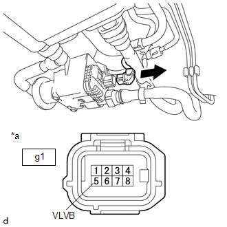
INSPECT CANISTER PUMP MODULE (POWER SOURCE FOR VENT VALVE) |
|
*a |
Front view of wire harness connector (to Canister Pump Module) |
(a) Turn the ignition switch off.
(b) Disconnect the canister pump module connector.
(c) Turn the ignition switch to ON.
(d) Measure the voltage according to the value(s) in the table below.
|
Tester Connection |
Switch Condition |
Specified Condition |
Suspected Trouble Area |
Proceed to |
|---|---|---|---|---|
|
g1-5 (VLVB) - Body ground |
Ignition switch ON |
11 to 14 V |
|
A |
|
Below 3 V |
|
B |
| B |
|
|
|
35. |
INSPECT CANISTER PUMP MODULE (VENT VALVE OPERATION) |

|
*a |
Component without harness connected (Canister Pump Module) |
(a) Turn the ignition switch off.
(b) Disconnect the canister pump module connector.
(c) Apply the battery voltage to terminals VLVB and VGND of the canister pump module.
(d) Touch the canister pump module to confirm the vent valve operation.
|
Condition |
Tester Result |
Suspected Trouble Area |
Proceed to |
|---|---|---|---|
|
Apply battery voltage to terminals VLVB and VGND |
Operating |
|
A |
|
Not operating |
|
B |
| B |
|
|
|
36. |
CHECK HARNESS AND CONNECTOR (CANISTER PUMP MODULE - ECM) |
(a) Turn the ignition switch off.
(b) Disconnect the g1 canister pump module connector.
(c) Disconnect the A69 ECM connector.
(d) Measure the resistance according to the value(s) in the table below.
|
Tester Connection |
Condition |
Test Result |
Suspected Trouble Area |
Proceed to |
|---|---|---|---|---|
|
g1-1 (VGND) - A69-19 (VPMP) |
Always |
Below 1 Ω |
|
A |
|
10 kΩ or higher |
Wire harness or connector between ECM and canister pump module |
B |
| B |
|
|
|
37. |
INSPECT CANISTER (CHARCOAL FILTER INSIDE CANISTER) |
(a) Check for filter blockage in the canister.
Click here
OK:
No blockages in the canister.
| OK |
|
|
|
38. |
INSPECT NO. 1 CHARCOAL CANISTER FILTER (CANISTER ASSEMBLY) |
(a) Check for filter blockage in the No. 1 charcoal canister filter (Canister assembly).
Click here
OK:
No blockages in the No. 1 charcoal canister filter (Canister assembly).
| OK |
|
|
|
39. |
REPLACE CANISTER |
(a) Replace the canister.
Click here
NOTICE:
- When replacing the canister pump module, check the canister pump module interior, canister interior, No. 1 charcoal canister filter and related pipes for water, fuel and other liquids. If liquids are present, check for disconnections and/or cracks in the following: 1) the pipe from the air inlet port to the canister pump module; 2) the canister filter; 3) the pipe from the No. 1 charcoal canister filter to canister and 4) the fuel tank vent hose. If liquids are present in the canister interior, replace the canister, No. 1 charcoal canister filter and canister pump module together.
- Check for filter blockage in the canister and No. 1 charcoal canister filter. If the charcoal filter inside the canister or No. 1 charcoal canister filter is clogged, replace the canister, No. 1 charcoal canister filter and canister pump module together.
- Check for filter blockage in the canister filter. If the canister filter has blockages, replace the canister filter.

|
*1 |
Fuel Tank Vent Hose |
*2 |
Vent Hose |
|
*3 |
Air Inlet Port (behind Fuel Tank Filler Pipe Cover) |
*4 |
Canister Filter |
|
*5 |
Fuel Tank |
*6 |
Canister Assembly |
|
*7 |
Canister Pump Module |
*8 |
No. 1 Charcoal Canister Filter |
|
*a |
Inspection Area (Check for disconnection and/or cracks) |
- |
- |
| NEXT |
|
|
40. |
PERFORM EVAP SYSTEM CHECK (STEP 3/6) |
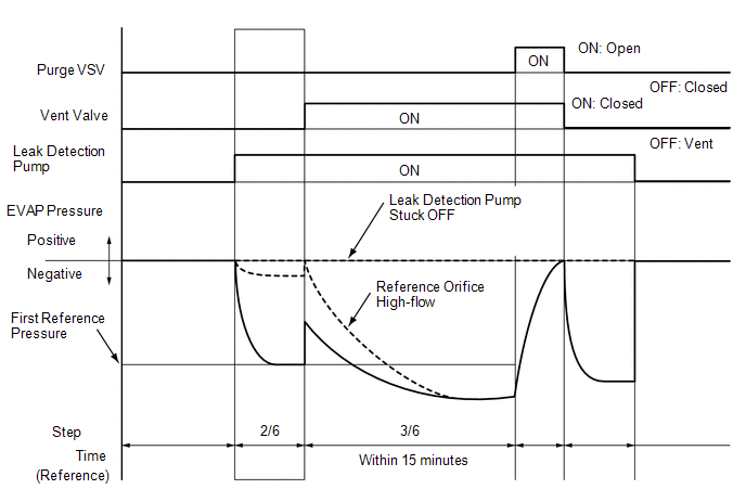
(a) Check the EVAP pressure in step 3/6.
|
DTC* |
Result |
Suspected Trouble Area |
Proceed to |
|---|---|---|---|
|
P043F00 |
EVAP pressure less than [reference pressure] measured in step 2/6 |
Reference orifice high-flow |
A |
|
P24007F |
EVAP pressure almost same as [reference pressure] measured in step 2/6 |
Leak detection pump stuck off |
B |
*: These DTCs are already present in the ECM when the vehicle arrives and are confirmed in the "Confirm DTC" procedure above.
HINT:
The first reference pressure is the value determined in step 2/6.
| A |
|
| B |
|
|
41. |
INSPECT CANISTER PUMP MODULE (VENT VALVE OPERATION) |
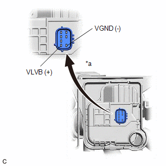
|
*a |
Component without harness connected (Canister Pump Module) |
(a) Turn the ignition switch off.
(b) Disconnect the g1 canister pump module connector.
(c) Apply the battery voltage to terminals VLVB and VGND of the canister pump module.
(d) Touch the canister pump module to confirm the vent valve operation.
|
Condition |
Tester Result |
Suspected Trouble Area |
Proceed to |
|---|---|---|---|
|
Apply battery voltage to terminals VLVB and VGND |
Operating |
|
A |
|
Not operating |
Vent valve |
B |
| B |
|
|
|
42. |
CHECK HARNESS AND CONNECTOR (CANISTER PUMP MODULE - ECM) |
(a) Turn the ignition switch off.
(b) Disconnect the g1 canister pump module connector.
(c) Disconnect the A69 ECM connector.
(d) Measure the resistance according to the value(s) in the table below.
Standard Resistance:
|
Tester Connection |
Condition |
Specified Condition |
|---|---|---|
|
g1-1 (VGND) - A69-19 (VPMP) |
Always |
Below 1 Ω |
|
g1-1 (VGND) or A69-19 (VPMP) - Body ground and other terminals |
Always |
10 kΩ or higher |
|
Result |
Suspected Trouble Area |
Proceed to |
|---|---|---|
|
OK |
|
A |
|
NG |
Wire harness or connector between ECM and canister pump module |
B |
| B |
|
|
|
43. |
CHECK HARNESS AND CONNECTOR (CANISTER PUMP MODULE - BODY GROUND) |
(a) Disconnect the g1 canister pump module connector.
(b) Measure the resistance according to the value(s) in the table below.
|
Tester Connection |
Condition |
Specified Condition |
Suspected Trouble Area |
Proceed to |
|---|---|---|---|---|
|
g1-4 (MGND) - Body ground |
Always |
Below 1 Ω |
|
A |
|
10 kΩ or higher |
Wire harness or connector between canister pump module and body ground |
B |
| B |
|
|
|
44. |
CHECK HARNESS AND CONNECTOR (CANISTER PUMP MODULE - ECM) |
(a) Disconnect the g1 canister pump module connector.
(b) Disconnect the A69 ECM connector.
(c) Measure the resistance according to the value(s) in the table below.
|
Tester Connection |
Condition |
Specified Condition |
Suspected Trouble Area |
Proceed to |
|---|---|---|---|---|
|
g1-3 (MTRB) - A69-21 (MPMP) |
Always |
Below 1 Ω |
|
A |
|
10 kΩ or higher |
Wire harness or connector between ECM and canister pump module |
B |
| B |
|
|
|
45. |
REPLACE CANISTER PUMP MODULE |
(a) Replace the canister pump module.
Click here
NOTICE:
- When replacing the canister pump module, check the canister pump module interior, canister interior, No. 1 charcoal canister filter and related pipes for water, fuel and other liquids. If liquids are present, check for disconnections and/or cracks in the following: 1) the pipe from the air inlet port to the canister pump module; 2) the canister filter; 3) the pipe from the No. 1 charcoal canister filter to canister and 4) the fuel tank vent hose. If liquids are present in the canister interior, replace the canister, No. 1 charcoal canister filter and canister pump module together.
- Check for filter blockage in the canister and No. 1 charcoal canister filter. If the charcoal filter inside the canister or No. 1 charcoal canister filter is clogged, replace the canister, No. 1 charcoal canister filter and canister pump module together.
- Check for filter blockage in the canister filter. If the canister filter has blockages, replace the canister filter.
|
*1 |
Fuel Tank Vent Hose |
*2 |
Vent Hose |
|
*3 |
Air Inlet Port (behind Fuel Tank Filler Pipe Cover) |
*4 |
Canister Filter |
|
*5 |
Fuel Tank |
*6 |
Canister Assembly |
|
*7 |
Canister Filter |
*8 |
No. 1 Charcoal Canister Filter |
|
*a |
Inspection Area (Check for disconnection and/or cracks) |
- |
- |
|
|
46. |
PERFORM EVAP SYSTEM CHECK (AUTOMATIC MODE) |
NOTICE:
- The Evaporative System Check (Automatic Mode) consists of 6 steps performed automatically by the Techstream. It takes a maximum of approximately 24 minutes.
- Do not perform the Evaporative System Check when the fuel tank is more than 85% full because the cut-off valve may be closed, making the fuel tank leak check unavailable.
- Do not run the engine in this step.
- When the temperature of the fuel is 35°C (95°F) or higher, a large amount of vapor forms and any check results become inaccurate. When performing an Evaporative System Check, keep the fuel temperature below 35°C (95°F).
(a) Connect the Techstream to the DLC3.
(b) Turn the ignition switch to ON.
(c) Turn the Techstream on.
(d) Clear the DTCs.
Click here
(e) Enter the following menus: Powertrain / Engine / Utility / Evaporative System Check / Automatic Mode.
(f) After the Evaporative System Check is completed, check for pending DTCs by entering the following menus: Powertrain / Engine / Trouble Codes.
|
Result |
Proceed to |
|---|---|
|
EVAP system DTCs are output |
A |
|
DTC is not output (Pending DTC is not output) |
B |
| A |
|
| B |
|
END |
|
47. |
CHECK TERMINAL VOLTAGE (CANISTER PUMP MODULE) |
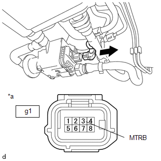
|
*a |
Front view of wire harness connector (to Canister Pump Module) |
(a) Turn the ignition switch off.
(b) Disconnect the canister pump module connector.
(c) Turn the ignition switch to ON.
(d) Measure the voltage according to the value(s) in the table below.
|
Tester Connection |
Switch Condition |
Test Result |
Suspected Trouble Area |
Proceed to |
|---|---|---|---|---|
|
g1-3 (MTRB) - Body ground |
Ignition switch ON |
9 to 14 V |
|
A |
|
Below 3 V |
|
B |
| B |
|
|
|
48. |
CHECK HARNESS AND CONNECTOR (CANISTER PUMP MODULE - BODY GROUND) |
(a) Turn the ignition switch off.
(b) Disconnect the g1 canister pump module connector.
(c) Measure the resistance according to the value(s) in the table below.
|
Tester Connection |
Condition |
Specified Condition |
Suspected Trouble Area |
Proceed to |
|---|---|---|---|---|
|
g1-4 (MGND) - Body ground |
Always |
Below 1 Ω |
Leak detection pump |
A |
|
10 kΩ or higher |
Wire harness or connector between canister pump module and body ground |
B |
| A |
|
| B |
|
|
49. |
CHECK HARNESS AND CONNECTOR (CANISTER PUMP MODULE - ECM) |
(a) Turn the ignition switch off.
(b) Disconnect the g1 canister pump module connector.
(c) Disconnect the A69 ECM connector.
(d) Measure the resistance according to the value(s) in the table below.
Standard Resistance:
|
Tester Connection |
Condition |
Specified Condition |
|---|---|---|
|
g1-3 (MTRB) - A69-21 (MPMP) |
Always |
Below 1 Ω |
|
g1-3 (MTRB) or A69-21 (MPMP) - Body ground and other terminals |
Always |
10 kΩ or higher |
|
Result |
Suspected Trouble Area |
Proceed to |
|---|---|---|
|
OK |
ECM |
A |
|
NG |
Wire harness or connector between ECM and canister pump module |
B |
| B |
|
|
|
50. |
REPLACE ECM |
(a) Replace the ECM.
Click here
| NEXT |
|
|
51. |
REPLACE CANISTER |
(a) Replace the canister.
Click here
NOTICE:
- When replacing the canister pump module, check the canister pump module interior, canister interior, No. 1 charcoal canister filter and related pipes for water, fuel and other liquids. If liquids are present, check for disconnections and/or cracks in the following: 1) the pipe from the air inlet port to the canister pump module; 2) the canister filter; 3) the pipe from the No. 1 charcoal canister filter to canister and 4) the fuel tank vent hose. If liquids are present in the canister interior, replace the canister, No. 1 charcoal canister filter and canister pump module together.
- Check for filter blockage in the canister and No. 1 charcoal canister filter. If the charcoal filter inside the canister or No. 1 charcoal canister filter is clogged, replace the canister, No. 1 charcoal canister filter and canister pump module together.
- Check for filter blockage in the canister filter. If the canister filter has blockages, replace the canister filter.

|
*1 |
Fuel Tank Vent Hose |
*2 |
Vent Hose |
|
*3 |
Air Inlet Port (behind Fuel Tank Filler Pipe Cover) |
*4 |
Canister Filter |
|
*5 |
Fuel Tank |
*6 |
Canister Assembly |
|
*7 |
Canister Pump Module |
*8 |
No. 1 Charcoal Canister Filter |
|
*a |
Inspection Area (Check for disconnection and/or cracks) |
- |
- |
| NEXT |
|
|
52. |
REPAIR OR REPLACE HARNESS OR CONNECTOR |
| NEXT |
|
|
53. |
INSPECT CANISTER PUMP MODULE (CANISTER PRESSURE SENSOR CIRCUIT) |
(a) Check the canister pressure sensor circuit, referring to DTC P045011 canister pressure sensor circuit inspection procedure.
Click here
|
|
54. |
PERFORM EVAP SYSTEM CHECK (AUTOMATIC MODE) |
NOTICE:
- The Evaporative System Check (Automatic Mode) consists of 6 steps performed automatically by the Techstream. It takes a maximum of approximately 24 minutes.
- Do not perform the Evaporative System Check when the fuel tank is more than 85% full because the cut-off valve may be closed, making the fuel tank leak check unavailable.
- Do not run the engine in this step.
- When the temperature of the fuel is 35°C (95°F) or higher, a large amount of vapor forms and any check results become inaccurate. When performing an Evaporative System Check, keep the fuel temperature below 35°C (95°F).
(a) Connect the Techstream to the DLC3.
(b) Turn the ignition switch to ON.
(c) Turn the Techstream on.
(d) Clear the DTCs.
Click here
(e) Enter the following menus: Powertrain / Engine / Utility / Evaporative System Check / Automatic Mode.
(f) After the Evaporative System Check is completed, check for pending DTCs by entering the following menus: Powertrain / Engine / Trouble Codes.
HINT:
If no pending DTCs are found, the repair has been successfully completed.
| NEXT |
|
END |
|
|
|