- Not communicating since the start of the CAN bus check
- Communication occurred at least once since the start of the CAN bus check, but is currently not occurring.
| Last Modified: 08-28-2024 | 6.11:8.1.0 | Doc ID: RM100000001DIRQ |
| Model Year Start: 2019 | Model: Sienna | Prod Date Range: [08/2018 - ] |
| Title: NETWORKING: CAN COMMUNICATION SYSTEM: DIAGNOSIS SYSTEM; 2019 - 2020 MY Sienna [08/2018 - ] | ||
DIAGNOSIS SYSTEM
1. CHECK INSTALLED SYSTEMS (ECUS AND SENSORS) THAT USE CAN COMMUNICATION
(a) Systems (ECUs and sensors) that use CAN communication vary depending on the optional settings of the vehicle. Check which systems (ECUs and sensors) are installed on the vehicle.
|
Connected to |
Code |
ECU/Sensor Name |
Techstream Display |
Applicability |
|---|---|---|---|---|
|
- |
CGW |
Central Gateway ECU (Network Gateway ECU) |
CAN Gateway |
Installed on all vehicles |
|
V Bus |
DLC3 |
DLC3 |
- |
Installed on all vehicles |
|
Bus 2 |
ENG |
ECM |
ECM (Engine) |
Installed on all vehicles |
|
MET |
Combination Meter Assembly |
Combination Meter |
Installed on all vehicles |
|
|
EPS |
Steering column assembly (power steering ECU) |
Power Steering (EPS) |
Installed on all vehicles |
|
|
A/C |
Air Conditioning Amplifier Assembly |
Air Conditioning Amplifier |
Installed on all vehicles |
|
|
SMT |
Certification ECU (smart key ECU assembly) |
Certification (Smart) |
w/ Smart Key System |
|
|
MB |
Main Body ECU (Multiplex Network Body ECU) |
Main Body |
Installed on all vehicles |
|
|
BRK |
Brake Actuator Assembly (Skid Control ECU) |
Skid Control (ABS/VSC/TRAC) |
Installed on all vehicles |
|
|
SRS |
Airbag Sensor Assembly |
Airbag |
Installed on all vehicles |
|
|
STR |
Steering Angle Sensor (Spiral Cable with Sensor Sub-assembly) |
Spiral cable (Steering Angle Sensor) |
Installed on all vehicles |
|
|
AWD |
4 Wheel Drive Control ECU (4WD Control ECU) |
Four Wheel Drive Control |
for AWD |
|
|
PMN |
Power Management Control ECU |
Power Management |
w/ Smart Key System |
|
|
Bus 3 |
AV |
Radio and Display Receiver Assembly |
Display and Navigation (AVN) |
Installed on all vehicles |
|
DCM |
DCM (telematics transceiver) |
DCM |
w/ Telematics Transceiver |
|
|
Bus 5 |
CS |
Clearance warning ECU assembly |
Clearance Warning (Intuitive Parking Assist) |
w/ Intuitive Parking Assist System |
|
DS |
Driving support ECU assembly |
Driving Support (Cruise Control-ACC) |
w/ Toyota Safety Sense P |
|
|
F-CAM |
Forward Recognition Camera |
Front Camera Module |
w/ Toyota Safety Sense P |
|
|
F-MR |
Millimeter Wave Radar Sensor Assembly |
Front Radar |
w/ Toyota Safety Sense P |
|
|
BSM |
Blind Spot Monitor Sensor RH |
Blind Spot Monitor Master |
w/ Blind Spot Monitor System |
|
|
R-CA |
Rear television camera assembly |
Advanced Parking Guidance/Parking Assist Monitor |
w/ Panoramic View Monitor System |
|
|
PAC |
Parking Assist ECU |
Panoramic View Monitor |
w/ Panoramic View Monitor System |
|
|
Sub bus 1 |
F-DRL |
Outer Mirror Control ECU Assembly LH |
Front Door LH/L-Mirror (FL-Door 2/L-Mirror) |
w/ Seat Position Memory System |
|
F-DRR |
Outer Mirror Control ECU Assembly RH |
Front Door RH/R-Mirror (FR-Door 2/R-Mirror) |
w/ Seat Position Memory System |
|
|
DST |
Front Power Seat Switch LH (Power Seat Control ECU) |
D-Seat |
w/ Seat Position Memory System |
|
|
BKD |
Power Back Door Unit Assembly (Back Door ECU) |
Back Door |
w/ Power Back Door |
|
|
PSD-L |
Slide Door Motor Unit LH |
Rear Door LH (RL-Door) |
w/ Power Slide Door |
|
|
PSD-R |
Slide Door Motor Unit RH |
Rear Door RH (RR-Door) |
w/ Power Slide Door |
2. CAN BUS CHECK
HINT:
The ECUs and sensors that are properly connected to the CAN communication system can be displayed using the Techstream.
(a) Using the Techstream, select the CAN Bus Check screen.
NOTICE:
- It may be possible to select buses that do not have ECUs or sensors from the bus selection pull-down menu. This is not a malfunction. (This occurs when optional devices are not on a sub bus that is monitored by a gateway function equipped ECU.)
-
In the bus selection pull down menu, all buses applicable to the model are displayed (e.g. LIN communication buses are also displayed). Therefore, refer to the wiring diagrams to check the names of sub buses for CAN communication.
Click here
![2018 - 2020 MY Sienna [11/2017 - ]; NETWORKING: CAN COMMUNICATION SYSTEM: SYSTEM DIAGRAM](/t3Portal/stylegraphics/info.gif)
HINT:
Different connection statuses are indicated by the background color of ECUs and sensors that are displayed.
Explanation of CAN Bus Check Screen
|
Bus Type |
Background Color |
Connection Status |
|---|---|---|
|
Bus |
White |
Communication has been normal. |
|
Yellow |
Communication stop occurred at least once since the start of the CAN bus check, but communication is currently occurring (unstable communication). |
|
|
Red |
Currently not communicating (either of the following): |
|
|
Not displayed |
Either of the following:
|
|
|
Sub bus with a gateway function equipped ECU that does not memorize connected ECUs or sensors*2 |
White |
Communication has been normal since the start of the CAN bus check. |
|
Yellow |
Communication stop occurred at least once since the start of the CAN bus check, but communication is currently occurring (unstable communication). |
|
|
Red |
Communication occurred at least once since the start of the CAN bus check, but is currently not occurring. |
|
|
Not displayed |
Communication stop has continued since the start of the CAN bus check.*1 |
|
|
Sub bus with a gateway function equipped ECU that memorizes connected ECUs and sensors*3 |
White |
Communication has been normal. |
|
Yellow |
Communication stop occurred at least once since the start of the CAN bus check, but communication is currently occurring (unstable communication). |
|
|
Red |
Currently not communicating (either of the following):
|
|
|
Not displayed |
Either of the following:
|
- Gateway function equipped ECUs relay signals between ECUs and sensors connected to different buses.
- *1: An ECU or sensor is installed to the vehicle but is not displayed on the "Communication Bus Check" screen.
- *2: The gateway function equipped ECU does not memorize ECUs and sensors connected to its respective sub bus.
- *3: The gateway function equipped ECU memorizes ECUs and sensors connected to its respective sub bus.
- *4: When the central gateway ECU (network gateway ECU) has an internal malfunction or cannot communicate with the Techstream, the name of buses, sub buses, ECUs and sensors will not be displayed.
- *5: When no ECUs or sensors are connected to a bus, the message "There is no system found on the communication Bus." will be displayed.
- *6: When a gateway function equipped ECU cannot communicate with the central gateway ECU (network gateway ECU), the name of sub buses and ECUs or sensors connected to the sub bus will not be displayed.
- *7: When no ECUs or sensors are connected to the sub bus, the message "There is no system found on the communication Bus." will be displayed.
- If there is no communication between the Techstream and the vehicle, or no ECUs or sensors are displayed as connected, check the central gateway ECU (network gateway ECU) and V bus (the bus that connects the DLC3 to the central gateway ECU (network gateway ECU)) for malfunctions.
(b) Observe the connection response screen for approximately 2 minutes to check for a change in connection status of the connected ECUs and sensors.
HINT:
- If an open occurs in one of the lines of a CAN branch (except DLC3), output from the other branch line (the line that is not open) will be unstable and it may interfere with the response (display) of other ECUs and sensors.
- If the connection status changes during the inspection, repair the open in the branch line of the ECU or sensor that does not respond (is not detected) and then perform the CAN bus check again.
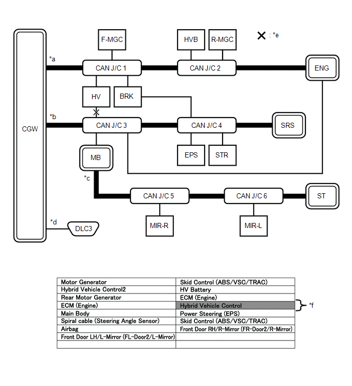
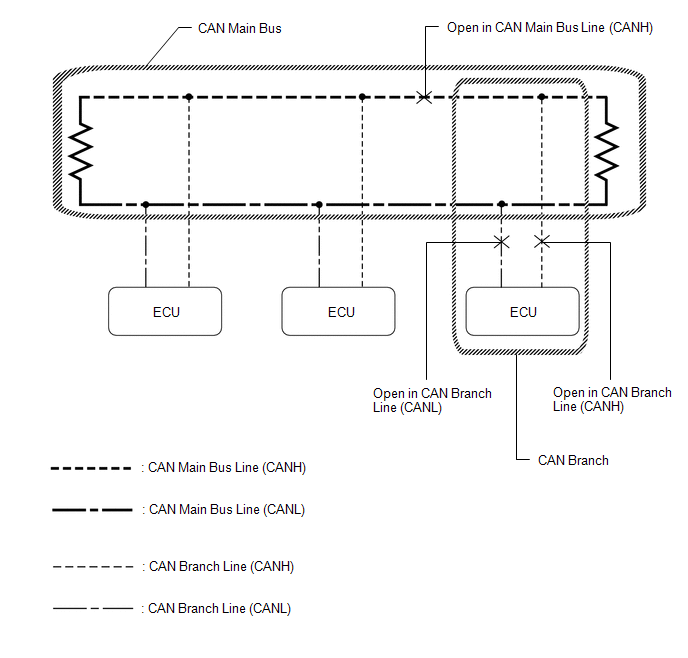
3. HOW TO INTERPRET CAN BUS CHECK SCREEN
(a) When a communication stop is currently occurring, the probable malfunctioning part can be determined from the CAN bus check and by using the following methods.
NOTICE:
The following CAN bus wiring diagram is provided only as an example. This wiring diagram is different from the actual wiring diagram for this vehicle.
HINT:
- When a communication stop is currently occurring, it is easier to determine the probable malfunctioning part from the CAN bus check rather than from communication DTCs.
- Wait for approximately 2 minutes after turning theignition switch ON (or simulate the driving conditions that enable the malfunction to be reproduced) and select "CAN Bus Check". Then observe the communication status of each ECU on the screen.
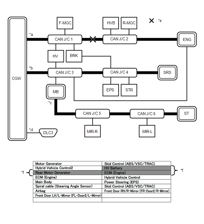
(b) If a communication error of only 1 ECU or sensor is indicated on the CAN Bus Check screen, a communication stop of the ECU or sensor is suspected.
Example: Open in both CAN branch lines of HV on the bus 4
|
*a |
Bus 2 |
*b |
Bus 4 |
|
*c |
Sub Bus |
*d |
V Bus |
|
*e |
Location of Malfunction |
*f |
Background color is red |
HINT:
When there are communication stops, ECUs that are present in the vehicle may not be displayed on the CAN Bus Check screen.
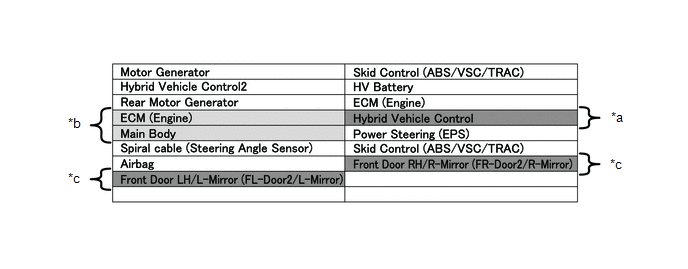
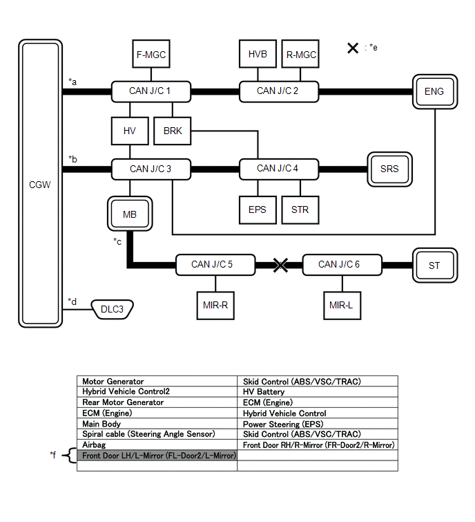
(c) If communication errors for multiple ECUs or sensors are indicated on the CAN Bus Check screen, then a communication stop of the ECU or sensor that shows a more serious communication stop (an ECU or sensor whose background color is red) is suspected.
Example: Open in a CAN branch line for HV on the bus 4
|
*a |
Background color is red |
*b |
Background color intermittently becomes yellow or red |
|
*c |
Not displayed or background color is yellow or red |
- |
- |
Explanation of CAN Bus Check Screen
|
Bus Type |
Background Color |
Connection Status |
|---|---|---|
|
Bus |
White |
Communication has been normal. |
|
Yellow |
Communication stop occurred at least once since the start of the CAN bus check, but communication is currently occurring (unstable communication). |
|
|
Red |
Currently not communicating (either of the following):
|
|
|
Not displayed |
Either of the following:
|
|
|
Sub bus with a gateway function equipped ECU that does not memorize connected ECUs or sensors*2 |
White |
Communication has been normal since the start of the CAN bus check. |
|
Yellow |
Communication stop occurred at least once since the start of the CAN bus check, but communication is currently occurring (unstable communication). |
|
|
Red |
Communication occurred at least once since the start of the CAN bus check, but is currently not occurring. |
|
|
Not displayed |
Communication stop has continued since the start of the CAN bus check.*1 |
|
|
Sub bus with a gateway function equipped ECU that memorizes connected ECUs and sensors*3 |
White |
Communication has been normal. |
|
Yellow |
Communication stop occurred at least once since the start of the CAN bus check, but communication is currently occurring (unstable communication). |
|
|
Red |
Currently not communicating (either of the following):
|
|
|
Not displayed |
Either of the following:
|
- Gateway function equipped ECUs relay signals between ECUs and sensors connected to different buses.
- *1: An ECU or sensor is installed to the vehicle but is not displayed on the "Communication Bus Check" screen.
- *2: The gateway function equipped ECU does not memorize ECUs and sensors connected to its respective sub bus.
- *3: The gateway function equipped ECU memorizes ECUs and sensors connected to its respective sub bus.
- *4: When the central gateway ECU (network gateway ECU) has an internal malfunction or cannot communicate with the Techstream, the name of buses, sub buses, ECUs and sensors will not be displayed.
- *5: When no ECUs or sensors are connected to a bus, the message "There is no system found on the communication Bus." will be displayed.
- *6: When a gateway function equipped ECU cannot communicate with the central gateway ECU (network gateway ECU), the name of sub buses and ECUs or sensors connected to the sub bus will not be displayed.
- *7: When no ECUs or sensors are connected to the sub bus, the message "There is no system found on the communication Bus." will be displayed.
- The example of the CAN Bus Check screen in the illustration shows the result of electrical noise on the CAN bus which is caused by an open in a CAN branch line of HV is also unstable. In addition, in this example, MB is equipped with a gateway function. Therefore, communication is also unstable between the Sub bus ECUs of MB and the bus 4.
- The example in the illustration shows that HV has a red background color on the CAN Bus Check screen. This indicates a more significant communication stop. In this case, a communication stop of HV is suspected.
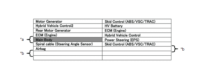
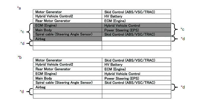
(d) If a communication error is indicated on both the bus 4 and Sub bus on the CAN Bus Check screen, suspect any communication stop displayed for the bus 4 first.
Example: Open in both CAN branch lines of MB on the bus 4
|
*a |
Background color is red |
*b |
Not displayed |
HINT:
- In the CAN bus check, it is possible to confirm the communication status of ECUs connected to the bus after connecting the Techstream to the DLC3. As for sub bus, it is possible to confirm which sub bus connected ECUs can communicate with a gateway function equipped ECU on the bus.
- If a gateway function equipped ECU has a communication error, ECUs connected to the gateway function equipped ECU are also affected, and communication stops will be indicated.
- The CAN Bus Check screen in the illustration shows that MB has a gateway function and a communication stop in MB is suspected.
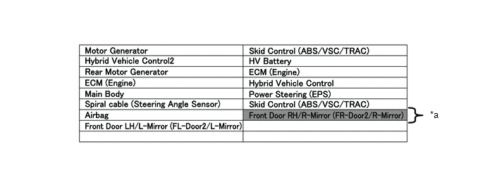
(e) If the CAN Bus Check screen indicates a communication stop only in the sub bus, a communication stop in the sub bus is suspected.
Example: Open in both CAN branch lines of MIR-R on the sub bus
|
*a |
Background color is red |
- |
- |
HINT:
- A communication error in a sub bus does not affect the other buses.
- When a gateway function equipped ECU has memorized the ECUs that are connected to the sub bus, if any of the ECUs connected to the gateway function equipped ECU has a communication error, the background color changes to yellow or red. (The displayed name will not disappear.)
(f) If both of the bus 2 main bus lines are open, ECUs or sensors that are located farther away from the central gateway ECU (network gateway ECU) than the open part will be displayed as a communication stop on the CAN Bus Check screen.
(In this case, HVB, R-MGC and ENG background color changes to red.)
|
*a |
Bus 2 |
*b |
Bus 4 |
|
*c |
Sub Bus |
*d |
V Bus |
|
*e |
Location of Malfunction |
*f |
Background color is red |
HINT:
If a communication error occurs in an ECU, it is not displayed on the CAN Bus Check screen even though the ECU is present.
(g) If both of the sub bus main bus lines are open, ECUs that are located farther away from the gateway function equipped ECU than the open part will be displayed as a communication stop on the CAN Bus Check screen.
(In this case, MIR-L background color changes to red.)
|
*a |
Bus 2 |
*b |
Bus 4 |
|
*c |
Sub Bus |
*d |
V Bus |
|
*e |
Location of Malfunction |
*f |
Background color is red |
(h) When any of the following malfunctions occur, CAN communication cannot be established and almost all ECUs and sensors on the bus show a communication error on the CAN Bus Check screen.
Details of Malfunction
|
Short between CAN lines (CANH and CANL) |
|
Short between a CAN line (CANH or CANL) and +B |
|
Short between a CAN line (CANH or CANL) and ground |
|
Open in a CAN main bus line |
|
*a |
When any of the following malfunctions occur on the bus 4 |
*b |
When any of the following malfunctions occur on a sub bus |
|
*c |
Background color is red |
*d |
Not displayed |
HINT:
- When a malfunction occurs in the bus, almost all ECUs and sensors on the bus and sub bus indicate a communication error (almost all ECUs are not displayed). As communication with the gateway function equipped ECU that is connected to the bus stops, communication from the ECUs connected to the sub bus that is monitored by the gateway function equipped ECU also stops (these ECUs are not displayed).
- When a malfunction occurs in a sub bus, almost all ECUs connected to the sub bus indicate a communication error.
- A communication error in a sub bus does not affect the other buses.
- The malfunctioning part can be determined by checking for a short circuit between CAN bus lines or between a CAN bus line and ground or +B short using an electrical tester.
(i) If a communication error of all ECUs and sensors is indicated on the CAN Bus Check screen, a communication stop of the V bus (DLC3 - central gateway ECU (network gateway ECU)) is suspected.
Open in both CAN branch lines in the V bus
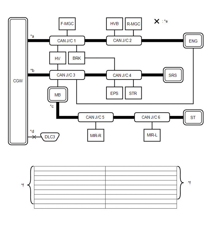
|
*a |
Bus 2 |
*b |
Bus 4 |
|
*c |
Sub Bus |
*d |
V Bus |
|
*e |
Location of Malfunction |
*f |
Not displayed |
HINT:
When there is no communication between the Techstream and the vehicle, no ECUs or sensors will be displayed.
4. DTC TABLE BY ECU
HINT:
- In the CAN communication system, CAN communication system DTCs stored by the ECU can be output by using the Techstream.
- If CAN communication system DTCs are output, the trouble cannot be determined solely from the DTCs. Perform troubleshooting according to "How to Proceed with Troubleshooting".
(a) BRAKE ACTUATOR ASSEMBLY (SKID CONTROL ECU)
HINT:
DTC communication uses the CAN communication system.
|
DTC Code |
Detection Item |
|---|---|
|
U0073 |
Control Module Communication Bus Off |
|
U0100 |
Lost Communication with ECM/PCM "A" |
|
U0123 |
Lost Communication with Yaw Rate Sensor Module |
|
U0124 |
Lost Communication with Lateral Acceleration Sensor Module |
|
U0126 |
Lost Communication with Steering Angle Sensor Module |
(b) MAIN BODY ECU (MULTIPLEX NETWORK BODY ECU)
HINT:
DTC communication uses the CAN communication system.
|
DTC Code |
Detection Item |
|---|---|
|
U0100 |
Lost Communication with ECM |
|
U0101 |
Lost Communication with TCM |
|
U0151 |
Lost Communication with Airbag ECU |
|
U0155 |
Lost Communication with Combination Meter |
|
U0200 |
Lost Communication with "Door Control Module B" |
|
U0201 |
Lost Communication with "Door Control Module C" |
|
U0202 |
Lost Communication with "Door Control Module D" |
|
U0199 |
Lost Communication with "Door Control Module A" |
|
U0208 |
Lost Communication with "Seat Control Module A" |
|
U0230 |
Lost Communication with Rear Gate Module |
|
U0327 |
Software Incompatibility with Vehicle Security Control Module |
|
U1002 |
Lost Communication with Gateway Module |
|
U1104 |
Lost Communication with Driving Support ECU |
|
U1133 |
Lost Communication with Power Management Module |
(c) CERTIFICATION ECU (SMART KEY ECU ASSEMBLY)
For vehicle with smart key system only.
HINT:
DTC communication uses the CAN communication system.
|
DTC Code |
Detection Item |
|---|---|
|
U0100 |
Lost Communication with ECM |
|
U0142 |
Lost Communication with Main Body ECU |
|
U0155 |
Lost Communication with Combination Meter |
(d) PARKING ASSIST ECU
For vehicle with panoramic view monitor system only.
HINT:
DTC communication uses the CAN communication system.
|
DTC Code |
Detection Item |
|---|---|
|
U0073 |
Control module communication bus off |
|
U0100 |
Lost Communication with ECM |
|
U0126 |
Lost Communication with Steering Angle Sensor Module |
|
U0129 |
Lost Communication with Skid Control ECU |
|
U0140 |
Lost Communication with Main Body ECU |
|
U0163 |
Lost Communication with Navigation Control Module |
|
U0265 |
Lost Communication with Parking Assist Monitor Module |
|
U1000 |
CAN Communication Failure (Message Registry) |
|
U1110 |
Lost Communication with Clearance Warning ECU |
(e) CLEARANCE WARNING ECU ASSEMBLY
For vehicle with intuitive parking assist system only.
HINT:
DTC communication uses the CAN communication system.
|
DTC Code |
Detection Item |
|---|---|
|
U0101 |
Lost Communication with TCM |
|
U0155 |
Lost Communication with Instrument Panel Cluster Control Module |
(f) AIR CONDITIONING AMPLIFIER ASSEMBLY
HINT:
DTC communication uses the CAN communication system.
|
DTC Code |
Detection Item |
|---|---|
|
U0100 |
Lost Communication with ECM |
|
U0131 |
Lost Communication with Power Steering ECU |
|
U0142 |
Lost Communication with Main Body ECU |
|
U0155 |
Lost Communication with Combination Meter |
(g) 4WD ECU ASSEMBLY
For AWD only.
HINT:
DTC communication uses the CAN communication system.
|
DTC Code |
Detection Item |
|---|---|
|
U0100 |
Lost Communication with ECM/PCM "A" |
|
U0123 |
Lost Communication with Yaw Rate Sensor Module |
|
U0124 |
Lost Communication with Lateral Acceleration Sensor Module |
|
U0126 |
Lost Communication with Steering Angle Sensor Module |
|
U0129 |
Lost Communication with Brake System Control Module |
(h) ECM
HINT:
DTC communication uses the CAN communication system.
|
DTC Code |
Detection Item |
|---|---|
|
U010487 |
Lost Communication with Cruise Control Module Missing Message |
|
U012287 |
Lost Communication with Vehicle Dynamics Control Module Missing Message |
|
U012387 |
Lost Communication with Yaw Rate Sensor Module Missing Message |
|
U012687 |
Lost Communication with Steering Angle Sensor Module Missing Message |
|
U015587 |
Lost Communication with Instrument Panel Cluster (IPC) Control Module |
|
U023587 |
Lost Communication with Cruise Control Front Distance Range Sensor Signal Sensor or Center Missing Message |
|
U110287 |
Lost Communication with Radar Sensor Missing Message |
(i) OUTER MIRROR CONTROL ECU ASSEMBLY LH AND OUTER MIRROR CONTROL ECU ASSEMBLY RH
For vehicle with seat position memory system only.
HINT:
DTC communication uses the CAN communication system.
|
DTC Code |
Detection Item |
|---|---|
|
U0142 |
Lost Communication with Main Body ECU |
(j) AIRBAG SENSOR ASSEMBLY
HINT:
The airbag sensor assembly is connected to the CAN communication system but CAN communication DTCs are not stored.
(k) DRIVING SUPPORT ECU ASSEMBLY
For vehicle with toyota safety sense p only.
HINT:
DTC communication uses the CAN communication system.
|
DTC Code |
Detection Item |
|---|---|
|
U0100 |
Lost Communication with ECM/PCM "A" |
|
U0125 |
Lost Communication with Yaw Rate Sensor Module |
|
U0126 |
Lost Communication with Steering Angle Sensor Module |
|
U0129 |
Lost Communication with Brake System Control Module |
|
U0235 |
Lost Communication with Cruise Control Front Distance Range Sensor |
|
U023A |
Lost Communication with Image Processing Module "A" |
|
U1002 |
Lost Communication with Gateway Module |
|
U1104 |
Lost Communication with Driving Support ECU |
(l) POWER MANAGEMENT CONTROL ECU
For vehicle with smart key system only.
HINT:
DTC communication uses the CAN communication system.
|
DTC Code |
Detection Item |
|---|---|
|
U0100 |
Lost Communication with ECM |
|
U0104 |
Lost Communication with Driving Support ECU |
|
U0114 |
Lost Communication with 4WD Control ECU |
|
U0233 |
Lost Communication with Blind Spot Monitor Master Module |
|
U1002 |
Lost Communication with Gateway Module |
|
U1110 |
Lost Communication with Clearance Sonar Module |
(m) FRONT POWER SEAT SWITCH LH
For vehicle with seat position memory system only.
HINT:
The front power seat switch LH is connected to the CAN communication system but CAN communication DTCs are not stored.
(n) CENTRAL GATEWAY ECU (NETWORK GATEWAY ECU)
HINT:
The central gateway ECU (network gateway ECU) is connected to the CAN communication system, but the central gateway ECU (network gateway ECU) does not store or output CAN communication DTCs.
(o) STEERING COLUMN ASSEMBLY (POWER STEERING ECU)
HINT:
DTC communication uses the CAN communication system.
|
DTC Code |
Detection Item |
|---|---|
|
U0100 |
Lost Communication with ECM |
|
U0129 |
Lost Communication with Brake System Control Module |
(p) STEERING ANGLE SENSOR (SPIRAL CABLE WITH SENSOR SUB-ASSEMBLY)
HINT:
The steering angle sensor (spiral cable with sensor sub-assembly) is connected to CAN communication system but CAN communication DTCs are not stored.
(q) COMBINATION METER ASSEMBLY
HINT:
DTC communication uses the CAN communication system.
|
DTC Code |
Detection Item |
|---|---|
|
U0100 |
Lost Communication with ECM/PCM "A" |
|
U0129 |
Lost Communication with Brake System Control Module |
|
U0131 |
Lost Communication with Power Steering Control Module |
|
U0151 |
Lost Communication with Airbag ECU |
|
U0163 |
Lost Communication with Navigation Control Module |
|
U023A |
Lost Communication with Image Processing Module "A" |
|
U1104 |
Lost Communication with Driving Support ECU |
(r) POWER BACK DOOR UNIT ASSEMBLY (BACK DOOR ECU)
For vehicle with power back door only.
HINT:
The power back door unit assembly (back door ECU) is connected to CAN communication system but CAN communication DTCs are not stored.
(s) SLIDE DOOR MOTOR UNIT LH AND SLIDE DOOR MOTOR UNIT RH
For vehicle with power slide door only.
HINT:
The slide door motor unit is connected to CAN communication system but CAN communication DTCs are not stored.
(t) FORWARD RECOGNITION CAMERA
For vehicle with toyota safety sense P only.
HINT:
DTC communication uses the CAN communication system.
|
DTC Code |
Detection Item |
|---|---|
|
U0100 |
Lost Communication with ECM/PCM "A" |
|
U0101 |
Lost Communication with TCM |
|
U0123 |
Lost Communication with Yaw Rate Sensor Module |
|
U0126 |
Lost Communication with Steering Angle Sensor Module |
|
U0129 |
Lost Communication with Brake System Control Module |
|
U0131 |
Lost Communication with Power Steering Control Module |
|
U0142 |
Lost Communication with Body Control Module "B" |
|
U0155 |
Lost Communication with Instrument Panel Cluster (IPC) Control Module (Combination Meter) |
|
U0235 |
Lost Communication with Cruise Control Front Distance Range Sensor |
|
U023A |
Lost Communication with Image Processing Module "A" |
|
U1104 |
Lost Communication with Driving Support ECU |
(u) BLIND SPOT MONITOR SENSOR RH
For vehicle with blind spot monitor system only.
HINT:
DTC communication uses the CAN communication system.
|
DTC Code |
Detection Item |
|---|---|
|
U0100 |
Lost Communication with ECM |
|
U0125 |
Lost Communication with Yaw Rate Sensor Module |
|
U0126 |
Lost Communication with Steering Angle Sensor Module |
|
U0129 |
Lost Communication with Brake System Control Module |
|
U0142 |
Lost Communication with Main Body ECU |
(v) RADIO AND DISPLAY RECEIVER ASSEMBLY
For radio and display type only.
HINT:
DTC communication uses the CAN communication system.
|
DTC Code |
Detection Item |
|---|---|
|
U0073 |
Sending Malfunction (Navigation to APGS) |
|
U0140 |
Lost Communication with Body Control Module |
|
U0155 |
Meter ECU Communication |
|
U0164 |
Air Conditioner ECU Communication |
|
U0198 |
Lost Communication with Telematics Control Module |
|
U1110 |
Clearance Sonar ECU Communication |
(w) REAR TELEVISION CAMERA ASSEMBLY
For vehicle with panoramic view monitor system only.
HINT:
DTC communication uses the CAN communication system.
|
DTC Code |
Detection Item |
|---|---|
|
U0100 |
Lost Communication with ECM/PCM "A" |
|
U0126 |
Lost Communication with Steering Angle Sensor Module |
|
U0140 |
Lost Communication with Body Control Module |
|
U0163 |
Lost Communication with Navigation Control Module |
|
U1000 |
CAN Communication Failure(Message Registry) |
|
U1110 |
Lost Communication with Intuitive Parking Assist Module |
(x) MILLIMETER WAVE RADAR SENSOR ASSEMBLY
For vehicle with toyota safety sense P only.
HINT:
The millimeter wave radar sensor assembly is connected to the CAN communication system, but the millimeter wave radar sensor assembly does not store or output CAN communication DTCs.
(y) DCM (TELEMATICS TRANSCEIVER)
For vehicle with telematics transceiver system only.
HINT:
DTC communication uses the CAN communication system.
|
DTC Code |
Detection Item |
|---|---|
|
U0142 |
Lost Communication with Body Control Module "B" |
|
U0155 |
Lost Communication with Instrument Panel Cluster (IPC) Control Module |
|
U0163 |
Lost Communication with Navigation Control Module |
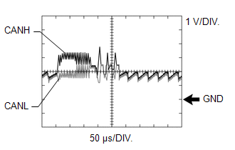
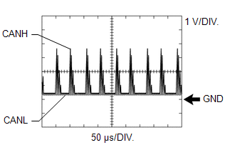
5. CAN BUS WAVEFORMS
HINT:
- The following waveforms are measured between terminals CANH and GND, and terminals CANL and GND of the central gateway ECU (network gateway ECU). (Use this as a reference for diagnosis of CAN communication lines.)
-
When malfunctions in multiple ECUs are suspected based on the CAN bus check and DTCs checked using the Techstream, check the resistance of the CAN bus using an ohmmeter first. If no problems are found, check the following waveforms.
Click here
- If a waveform is not similar to one of the following 3 patterns (Group 1), then an open in a CAN main bus line, an open in a CAN branch line, or a short between a CAN line (CANH or CANL) and ground is suspected (Group 2).
- Wiggle the connector and wire harness to check if the waveform changes.
(a) CAN bus waveforms (Group 1)
(1) Normal waveform
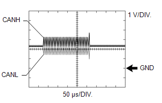
(2) Open in both of the lines (CANH and CANL) of a CAN branch
HINT:
- Waveforms (waveforms shown using dotted lines) are not present from an ECU or sensor connected to a CAN branch with an open circuit in both lines. (Waveforms from other ECUs or sensors are normal.)
- Because this waveform is similar to a normal waveform, instead of using the waveform, the malfunctioning part can be narrowed down by performing a CAN bus check.
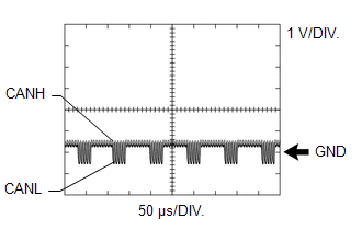
(3) Short between the CAN bus lines (CANH and CANL)
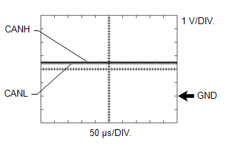
HINT:
- Waveforms disappear.
- If the malfunction is in an ECU, disconnecting the ECU will change the waveform. If the waveform does not change, a malfunction in the wire harness is suspected.
(b) CAN bus waveforms (reference) (Group 2)
NOTICE:
The following CAN bus waveforms can be used only as reference. The actual measured waveform may differ significantly depending on the location of the open or short circuit.
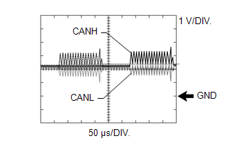
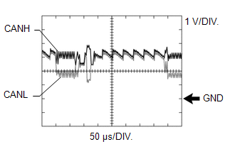
(1) Open in a CAN branch line (CANH)
HINT:
- An abnormal waveform is output from an ECU with an open in one of its CAN branch lines. Because this abnormal output interferes with the signals from other ECUs, the output of other ECUs will also appear abnormal.
- Narrow down the malfunctioning part by checking DTCs or performing a CAN bus check, or by checking waveform changes when ECUs or sensors are disconnected. The waveform will change to one for an open in both sides of a CAN branch when the ECU or sensor with an open CAN branch line is disconnected.
(2) Open in a CAN branch line (CANL)
HINT:
- An abnormal waveform is output from an ECU with an open in one of its CAN branch lines. Because this abnormal output interferes with the signals from other ECUs, the output of other ECUs will also appear abnormal.
- Narrow down the malfunctioning part by checking DTCs or performing a CAN bus check, or by checking waveform changes when ECUs or sensors are disconnected. The waveform will change to one for an open in both sides of a CAN branch when the ECU or sensor with an open CAN branch line is disconnected.
(3) Open in a CAN main bus line (CANH)
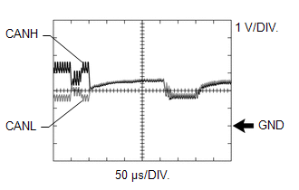
HINT:
- Waveforms of ECUs or sensors that are closer to the DLC3 than the open part are almost normal.
- Waveforms of ECUs or sensors that are on the opposite side of the DLC3 from the open part are abnormal.
- An open in a CAN main bus line can be confirmed by measuring the resistance between the CANH and CANL terminals of any CAN branch.
(4) Short between a CAN bus line (CANH) and ground
HINT:
- Narrow down the shorted part by checking for waveform changes when disconnecting connectors from the CAN junction connectors or when disconnecting ECUs or sensors.
- A short to ground in the CANH line can be confirmed by measuring the resistance between CANH and ground using an ohmmeter.
(5) Short between a CAN bus line (CANL) and ground
HINT:
- Narrow down the shorted part by checking for waveform changes when disconnecting connectors from the CAN junction connectors or when disconnecting ECUs or sensors.
- A short to ground in the CANL line can be confirmed by measuring the resistance between CANL and ground using an ohmmeter.
|
|
|