| Last Modified: 08-28-2024 | 6.11:8.1.0 | Doc ID: RM100000001DIRP |
| Model Year Start: 2019 | Model: Sienna | Prod Date Range: [08/2018 - ] |
| Title: NETWORKING: CAN COMMUNICATION SYSTEM: TERMINALS OF ECU; 2019 - 2020 MY Sienna [08/2018 - ] | ||
TERMINALS OF ECU
NOTICE:
-
After turning the ignition switch off, waiting time may be required before disconnecting the cable from the negative (-) battery terminal. Therefore, make sure to read the disconnecting the cable from the negative (-) battery terminal notices before proceeding with work.
Click here
![2017 - 2020 MY Sienna [08/2016 - ]; INTRODUCTION: REPAIR INSTRUCTION: PRECAUTION](/t3Portal/stylegraphics/info.gif)
- Before measuring the resistance of the CAN bus, turn the ignition switch off and leave the vehicle for 1 minute or more without operating the key or any switches, or opening or closing the doors. After that, disconnect the cable from the negative (-) battery terminal and leave the vehicle for 1 minute or more before measuring the resistance.
- This section describes the standard values for all CAN related components.
HINT:
-
The systems (ECUs and sensors) that use CAN communication vary depending on the vehicle and optional equipment. Check which systems (ECUs and sensors) are installed to the vehicle.
Click here
- Operating the ignition switch, any other switches or a door triggers related ECU and sensor communication on the CAN. This communication will cause the resistance value to change.
- Even after DTCs are cleared, if a DTC is stored again after driving the vehicle for a while, the malfunction may be occurring due to vibration of the vehicle. In such a case, wiggling the ECUs or wire harness while performing the inspection below may help determine the cause of the malfunction.
1. NO. 1 CAN JUNCTION CONNECTOR
(a) Check the No. 1 CAN junction connector.
HINT:
Connectors that connect to the CAN junction connector can be distinguished by the color of their CAN bus lines. When the connectors have been disconnected from the CAN junction connector, reconnecting the connectors to non-original positions on the CAN junction connector does not affect system performance. However, it is preferred to reconnect the connectors to their original positions to avoid negative effects on the wiring such as tension on the wire harnesses, and to make future maintenance easier.
(1) Connection diagram

|
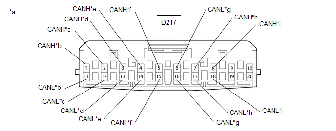
*a |
Component with harness connected (No. 1 CAN Junction Connector) |
*b |
to No. 1 CAN Junction Terminal |
|
*c |
to Outer Mirror Control ECU Assembly RH (w/ Seat Position Memory System) |
*d |
to Slide Door Motor Unit RH (w/ Power Slide Door) |
|
*e |
to Main Body ECU (Multiplex Network Body ECU) |
*f |
to Front Power Seat Switch LH (w/ Seat Position Memory System) |
|
*g |
to Power Back Door Unit Assembly (back door ECU) (w/ Power Back Door) |
*h |
to Slide Door Motor Unit LH (w/ Power Slide Door) |
|
*i |
to Outer Mirror Control Assembly LH (w/ Seat Position Memory System) |
- |
- |
(2) Check the connection diagram of the components which are connected to the No. 1 CAN junction connector.
|
Terminal No. (Symbol) |
Wiring Color |
Connected to |
|---|---|---|
|
D216-1 (CANH) |
GR |
No. 1 CAN junction terminal |
|
D216-11 (CANL) |
W |
|
|
D216-2 (CANH) |
V |
Outer mirror control ECU assembly RH*1 |
|
D216-12 (CANL) |
W |
|
|
D216-3 (CANH) |
L |
Slide door motor unit RH*2 |
|
D216-13 (CANL) |
W |
|
|
D216-4 (CANH) |
LG |
Main body ECU (multiplex network body ECU) |
|
D216-14 (CANL) |
W |
|
|
D216-5 (CANH) |
G |
Front power seat switch LH*1 |
|
D216-15 (CANL) |
W |
|
|
D216-6 (CANH) |
B |
Power back door unit assembly (back door ECU)*3 |
|
D216-16 (CANL) |
W |
|
|
D216-7 (CANH) |
R |
Slide door motor unit LH*2 |
|
D216-17 (CANL) |
W |
|
|
D216-8 (CANH) |
P |
Outer mirror control assembly LH*1 |
|
D216-18 (CANL) |
W |
- *1: w/ Seat Position Memory System
- *2: w/ Power Slide Door
- *3: w/ Power Back Door
2. NO. 2 CAN JUNCTION CONNECTOR
(a) Check the No. 2 CAN junction connector.
HINT:
Connectors that connect to the CAN junction connector can be distinguished by the color of their CAN bus lines. When the connectors have been disconnected from the CAN junction connector, reconnecting the connectors to non-original positions on the CAN junction connector does not affect system performance. However, it is preferred to reconnect the connectors to their original positions to avoid negative effects on the wiring such as tension on the wire harnesses, and to make future maintenance easier.
(1) Connection diagram
|
*a |
Component with harness connected (to No. 2 CAN Junction Connector) |
*b |
to No. 3 CAN Junction Connector |
|
*c |
to Central Gateway ECU (Network Gateway ECU) |
*d |
to Millimeter Wave Radar Sensor Assembly (w/ Toyota Safety Sense P) |
|
*e |
to Forward Recognition Camera (w/ Toyota Safety Sense P) |
*f |
to Clearance Warning ECU Assembly (w/ Blind Spot Monitor System) |
|
*g |
to Parking Assist ECU (w/ Intuitive Parking Assist System) |
*h |
to Driving Support ECU Assembly (w/ Intuitive Parking Assist System) |
|
*i |
to Blind Spot Monitor Sensor LH (w/ Toyota Safety Sense P) |
- |
- |
(2) Check the connection diagram of the components which are connected to the No. 2 CAN junction connector.
|
Terminal No. (Symbol) |
Wiring Color |
Connected to |
|---|---|---|
|
D217-1 (CANH) |
B |
No. 3 CAN junction connector |
|
D217-11 (CANL) |
W |
|
|
D217-2 (CANH) |
V |
Central Gateway ECU (Network Gateway ECU) |
|
D217-12 (CANL) |
W |
|
|
D217-3 (CANH) |
GR |
Millimeter wave radar sensor assembly*1 |
|
D217-13 (CANL) |
W |
|
|
D217-4 (CANH) |
G |
Forward recognition camera*1 |
|
D217-14 (CANL) |
W |
|
|
D217-5 (CANH) |
P |
Blind spot monitor sensor RH*2 |
|
D217-15 (CANL) |
W |
|
|
D217-6 (CANH) |
LG |
Clearance warning ECU assembly*3 |
|
D217-16 (CANL) |
W |
|
|
D217-7 (CANH) |
L |
Parking assist ECU*4 |
|
D217-17 (CANL) |
W |
|
|
D217-8 (CANH) |
R |
Driving support ECU assembly*1 |
|
D217-18 (CANL) |
W |
- *1: w/ Toyota Safety Sense P
- *2: w/ Blind Spot Monitor System
- *3: w/ Intuitive Parking Assist System
- *4: w/ Panoramic View Monitor System
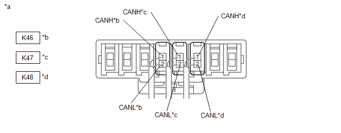
3. NO. 3 CAN JUNCTION CONNECTOR
(a) Check the No. 3 CAN junction connector.
HINT:
Connectors that connect to the CAN junction connector can be distinguished by the color of their CAN bus lines. When the connectors have been disconnected from the CAN junction connector, reconnecting the connectors to non-original positions on the CAN junction connector does not affect system performance. However, it is preferred to reconnect the connectors to their original positions to avoid negative effects on the wiring such as tension on the wire harnesses, and to make future maintenance easier.
(1) Connection diagram
|
*a |
Component with harness connected (to No. 3 CAN Junction Connector) |
*b |
to No. 2 CAN Junction Connector |
|
*c |
to No. 2 CAN Junction Terminal |
*d |
to Rear Television Camera Assembly (w/ Rear View Monitor System) |
(2) Check the connection diagram of the components which are connected to the No. 3 CAN junction connector.
|
Terminal No. (Symbol) |
Wiring Color |
Connected to |
|---|---|---|
|
K46-1 (CANH) |
B |
No. 2 CAN junction connector |
|
K46-2 (CANL) |
W |
|
|
K47-1 (CANH) |
L |
No. 2 CAN junction terminal |
|
K47-2 (CANL) |
W |
|
|
K48-1 (CANH) |
P |
Rear television camera assembly* |
|
K48-2 (CANL) |
W |
- *: w/ Rear View Monitor System
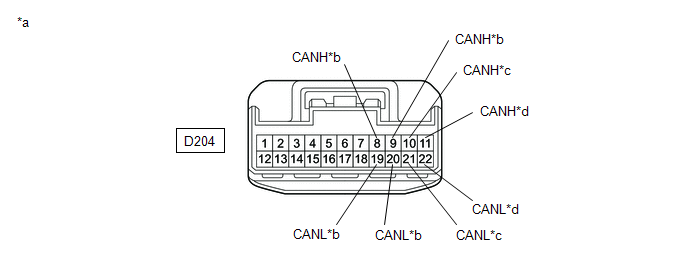
4. NO. 4 JUNCTION CONNECTOR
(a) Check the No. 4 junction connector.
(1) Connection diagram.
|
*a |
Front view of wire harness connector (to No. 4 Junction Connector) |
*b |
to Central Gateway ECU (Network Gateway ECU) |
|
*c |
to DCM (Telematics Transceiver) (w/ Telematics Transceiver) |
*d |
to Radio and Display Receiver Assembly |
|
No. 4 Junction Connector |
Wiring Color |
Connect to |
|---|---|---|
|
D204-8 (CANH) |
B |
Central Gateway ECU (Network Gateway ECU) |
|
D204-19 (CANL) |
W |
|
|
D204-10 (CANH) |
LG |
DCM (telematics transceiver)* |
|
D204-21 (CANL) |
W |
|
|
D204-11 (CANH) |
BR |
Radio and display receiver assembly |
|
D204-22 (CANL) |
W |
|
|
D204-9 (CANH) |
L |
Central Gateway ECU (Network Gateway ECU) |
|
D204-20 (CANL) |
W |
- *: w/ Telematics Transceiver
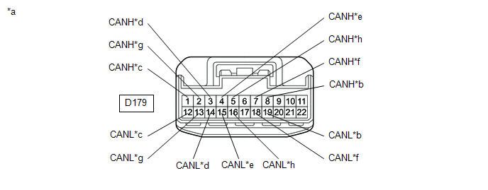
5. NO. 5 JUNCTION CONNECTOR
(a) Check the No. 5 junction connector.
(1) Connection diagram.
|
*a |
Component with harness connected (to No. 5 Junction Connector) |
*b |
to No. 6 Junction Connector |
|
*c |
to Brake Actuator Assembly (Skid Control ECU) |
*d |
to Certification ECU (Smart Key ECU Assembly) (w/ Smart Key System) |
|
*e |
to Power Management Control ECU (w/ Smart Key System) |
*f |
to Combination Meter Assembly |
|
*g |
to Air Conditioning Amplifier Assembly |
*h |
to Central Gateway ECU (Network Gateway ECU) |
|
No. 5 Junction Connector |
Wiring Color |
Connect to |
|---|---|---|
|
D179-8 (CANH) |
V |
No. 6 junction connector |
|
D179-19 (CANL) |
W |
|
|
D179-1 (CANH) |
R |
Brake actuator assembly (skid control ECU) |
|
D179-12 (CANL) |
W |
|
|
D179-3 (CANH) |
B |
Certification ECU (smart key ECU assembly)* |
|
D179-14 (CANL) |
W |
|
|
D179-4 (CANH) |
LG |
Power management control ECU* |
|
D179-15 (CANL) |
W |
|
|
D179-7 (CANH) |
P |
Combination meter assembly |
|
D179-18 (CANL) |
W |
|
|
D179-2 (CANH) |
G |
Air conditioning amplifier assembly |
|
D179-13 (CANL) |
W |
|
|
D179-5 (CANH) |
SB |
Central Gateway ECU (Network Gateway ECU) |
|
D179-16 (CANL) |
W |
- *: w/ Smart Key System
6. NO. 6 JUNCTION CONNECTOR
(a) Check the No. 6 junction connector.
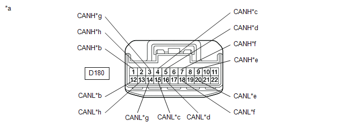
(1) Connection diagram.
|
*a |
Component with harness connected (to No. 6 Junction Connector) |
*b |
to No. 5 Junction Connector |
|
*c |
to Main Body ECU (Multiplex Network Body ECU) |
*d |
to 4WD ECU Assembly (for AWD) |
|
*e |
to Airbag Sensor Assembly |
*f |
to ECM |
|
*g |
to Steering Column Assembly (Power Steering ECU) |
*h |
to Steering Angle Sensor (Spiral Cable with Sensor Sub-assembly) |
|
No. 6 Junction Connector |
Wiring Color |
Connect to |
|---|---|---|
|
D180-1 (CANH) |
V |
No. 5 junction connector |
|
D180-12 (CANL) |
W |
|
|
D180-4 (CANH) |
GR |
Main body ECU (multiplex network body ECU) |
|
D180-15 (CANL) |
W |
|
|
D180-5 (CANH) |
L |
4WD ECU assembly* |
|
D180-16 (CANL) |
W |
|
|
D180-9 (CANH) |
B |
Airbag sensor assembly |
|
D180-20 (CANL) |
W |
|
|
D180-7 (CANH) |
G |
ECM |
|
D180-18 (CANL) |
W |
|
|
D180-3 (CANH) |
B |
Steering column assembly (power steering ECU) |
|
D180-14 (CANL) |
W |
|
|
D180-2 (CANH) |
L |
Steering angle sensor (spiral cable with sensor sub-assembly) |
|
D180-13 (CANL) |
Y |
- *: for AWD
7. CAN JUNCTION TERMINAL
(a) NO. 1 CAN JUNCTION TERMINAL

|
*a |
to No. 1 CAN Junction Connector |
- |
- |
|
No. 1 CAN Junction Terminal |
Wiring Color |
Connect to |
|---|---|---|
|
D183-2 (CANL) |
W |
to No. 1 CAN junction connector |
|
D183-3 (CANH) |
GR |
(b) NO. 2 CAN JUNCTION TERMINAL

|
*a |
to No. 3 CAN Junction Connector |
- |
- |
|
No. 2 CAN Junction Terminal |
Wiring Color |
Connect to |
|---|---|---|
|
K45-2 (CANL) |
W |
to No. 3 CAN junction connector |
|
K45-3 (CANH) |
L |
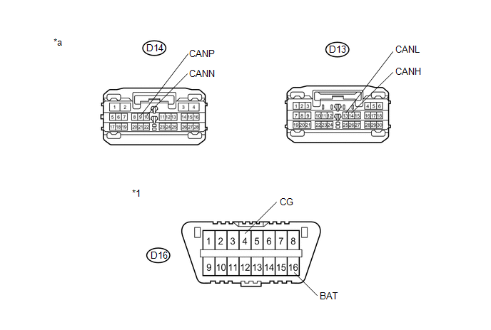
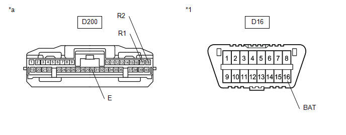
8. DLC3
(a) Disconnect the cable from the negative (-) battery terminal.
(b) Measure the resistance according to the value(s) in the table below.
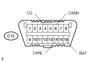
Standard Resistance:
|
Terminal No. (Symbol) |
Wiring Color |
Terminal Description |
Condition |
Specified Condition |
|---|---|---|---|---|
|
D16-6 (CANH) - D16-14 (CANL) |
P - W |
HIGH-level CAN bus line - LOW-level CAN bus line |
Cable disconnected from negative (-) battery terminal |
54 to 69 Ω |
|
D16-6 (CANH) - D16-4 (CG) |
P - W-B |
HIGH-level CAN bus line - Ground |
Cable disconnected from negative (-) battery terminal |
200 Ω or higher |
|
D16-14 (CANL) - D16-4 (CG) |
W - W-B |
LOW-level CAN bus line - Ground |
Cable disconnected from negative (-) battery terminal |
200 Ω or higher |
|
D16-6 (CANH) - D16-16 (BAT) |
P - B |
HIGH-level CAN bus line - Battery positive (+) |
Cable disconnected from negative (-) battery terminal |
6 kΩ or higher |
|
D16-14 (CANL) - D16-16 (BAT) |
W - B |
LOW-level CAN bus line - Battery positive (+) |
Cable disconnected from negative (-) battery terminal |
6 kΩ or higher |
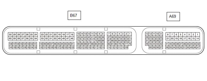
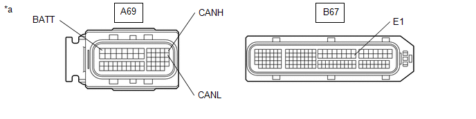
9. ECM
(a) Disconnect the cable from the negative (-) battery terminal.
(b) Disconnect the ECM connectors.
|
*a |
Front view of wire harness connector (to ECM) |
- |
- |
(c) Measure the resistance according to the value(s) in the table below.
Standard Resistance:
|
Terminal No. (Symbol) |
Wiring Color |
Terminal Description |
Condition |
Specified Condition |
|---|---|---|---|---|
|
A69-13 (CANH) - A69-26 (CANL) |
B - W |
HIGH-level CAN bus line - LOW-level CAN bus line |
Cable disconnected from negative (-) battery terminal |
108 to 132 Ω |
|
A69-13 (CANH) - B67-53 (E1) |
B - BR |
HIGH-level CAN bus line - Ground |
Cable disconnected from negative (-) battery terminal |
200 Ω or higher |
|
A69-26 (CANL) - B67-53 (E1) |
W - BR |
LOW-level CAN bus line - Ground |
Cable disconnected from negative (-) battery terminal |
200 Ω or higher |
|
A69-13 (CANH) - A69-1 (BATT) |
B - L |
HIGH-level CAN bus line - Battery positive (+) |
Cable disconnected from negative (-) battery terminal |
6 kΩ or higher |
|
A69-26 (CANL) - A69-1 (BATT) |
W - L |
LOW-level CAN bus line - Battery positive (+) |
Cable disconnected from negative (-) battery terminal |
6 kΩ or higher |
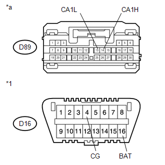
10. POWER MANAGEMENT CONTROL ECU (w/ Smart Key System)
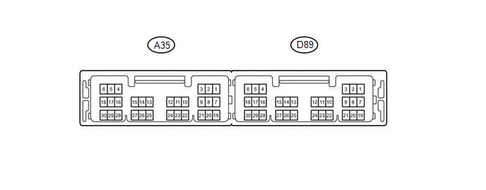
(a) Disconnect the cable from the negative (-) battery terminal.
(b) Disconnect the power management control ECU connector.
|
*1 |
DLC3 |
|
*a |
Front view of wire harness connector (to Power Management Control ECU) |
(c) Measure the resistance according to the value(s) in the table below.
Standard Resistance:
|
Terminal No. (Symbol) |
Wiring Color |
Terminal Description |
Condition |
Specified Condition |
|---|---|---|---|---|
|
D89-14 (CA1H) - D89-13 (CA1L) |
LG - W |
HIGH-level CAN bus line - LOW-level CAN bus line |
Cable disconnected from negative (-) battery terminal |
54 to 69 Ω |
|
D89-14 (CA1H) - D16-4 (CG) |
LG - W-B |
HIGH-level CAN bus line - Ground |
Cable disconnected from negative (-) battery terminal |
200 Ω or higher |
|
D89-13 (CA1L) - D16-4 (CG) |
W - W-B |
LOW-level CAN bus line - Ground |
Cable disconnected from negative (-) battery terminal |
200 Ω or higher |
|
D89-14 (CA1H) - D16-16 (BAT) |
LG - B |
HIGH-level CAN bus line - Battery positive (+) |
Cable disconnected from negative (-) battery terminal |
6 kΩ or higher |
|
D89-13 (CA1L) - D16-16 (BAT) |
W - B |
LOW-level CAN bus line - Battery positive (+) |
Cable disconnected from negative (-) battery terminal |
6 kΩ or higher |
11. CENTRAL GATEWAY ECU (NETWORK GATEWAY ECU)
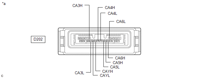
|
*a |
Component without harness connected (Central Gateway ECU (Network Gateway ECU)) |
- |
- |
(a) Disconnect the cable from the negative (-) battery terminal.
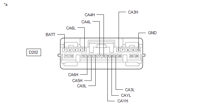
(b) Disconnect the D202 central gateway ECU (network gateway ECU) connector.
|
*a |
Front view of wire harness connector (to Central Gateway ECU (Network Gateway ECU)) |
- |
- |
(c) Measure the resistance according to the value(s) in the table below.
Standard Resistance:
Diagnosis Bus Branch Lines (DLC3 - Central gateway ECU (network gateway ECU))
|
Terminal No. (Symbol) |
Wiring Color |
Terminal Description |
Condition |
Specified Condition |
|---|---|---|---|---|
|
D202-14 (CA6H) - D202-5 (CA6L) |
P - W |
HIGH-level CAN bus line - LOW-level CAN bus line |
Cable disconnected from negative (-) battery terminal |
1 MΩ or higher |
|
D202-14 (CA6H) - D202-10 (GND) |
P - W-B |
HIGH-level CAN bus line - Ground |
Cable disconnected from negative (-) battery terminal |
200 Ω or higher |
|
D202-5 (CA6L) - D202-10 (GND) |
W - W-B |
LOW-level CAN bus line - Ground |
Cable disconnected from negative (-) battery terminal |
200 Ω or higher |
|
D202-14 (CA6H) - D202-1 (BATT) |
P - B |
HIGH-level CAN bus line - Battery positive (+) |
Cable disconnected from negative (-) battery terminal |
6 kΩ or higher |
|
D202-5 (CA6L) - D202-1 (BATT) |
W - B |
LOW-level CAN bus line - Battery positive (+) |
Cable disconnected from negative (-) battery terminal |
6 kΩ or higher |
Bus 2 Main Lines
|
Terminal No. (Symbol) |
Wiring Color |
Terminal Description |
Condition |
Specified Condition |
|---|---|---|---|---|
|
D202-18 (CA4H) - D202-17 (CA4L) |
SB - W |
HIGH-level CAN bus line - LOW-level CAN bus line |
Cable disconnected from negative (-) battery terminal |
108 to 132 Ω |
|
D202-18 (CA4H) - D202-10 (GND) |
SB - W-B |
HIGH-level CAN bus line - Ground |
Cable disconnected from negative (-) battery terminal |
200 Ω or higher |
|
D202-17 (CA4L) - D202-10 (GND) |
W - W-B |
LOW-level CAN bus line - Ground |
Cable disconnected from negative (-) battery terminal |
200 Ω or higher |
|
D202-18 (CA4H) - D202-1 (BATT) |
SB - B |
HIGH-level CAN bus line - Battery positive (+) |
Cable disconnected from negative (-) battery terminal |
6 kΩ or higher |
|
D202-17 (CA4L) - D202-1 (BATT) |
W - B |
LOW-level CAN bus line - Battery positive (+) |
Cable disconnected from negative (-) battery terminal |
6 kΩ or higher |
Bus 3 Main Lines
|
Terminal No. (Symbol) |
Wiring Color |
Terminal Description |
Condition |
Specified Condition |
|---|---|---|---|---|
|
D202-6 (CA3H) - D202-19 (CAYH) |
L - B |
HIGH-level CAN bus line - HIGH-level CAN bus line |
Cable disconnected from negative (-) battery terminal |
Below 1 Ω |
|
D202-21 (CA3L) - D202-20 (CAYL) |
W - W |
LOW-level CAN bus line - LOW-level CAN bus line |
Cable disconnected from negative (-) battery terminal |
Below 1 Ω |
|
D202-6 (CA3H) - D202-10 (GND) |
L - W-B |
HIGH-level CAN bus line - Ground |
Cable disconnected from negative (-) battery terminal |
200 Ω or higher |
|
D202-21 (CA3L) - D202-10 (GND) |
W - W-B |
LOW-level CAN bus line - Ground |
Cable disconnected from negative (-) battery terminal |
200 Ω or higher |
|
D202-6 (CA3H) - D202-1 (BATT) |
L - B |
HIGH-level CAN bus line - Battery positive (+) |
Cable disconnected from negative (-) battery terminal |
6 kΩ or higher |
|
D202-21 (CA3L) - D202-1 (BATT) |
W - B |
LOW-level CAN bus line - Battery positive (+) |
Cable disconnected from negative (-) battery terminal |
6 kΩ or higher |
Bus 5 Main Lines
|
Terminal No. (Symbol) |
Wiring Color |
Terminal Description |
Condition |
Specified Condition |
|---|---|---|---|---|
|
D202-15 (CA5H) - D202-16 (CA5L) |
V - W |
HIGH-level CAN bus line - LOW-level CAN bus line |
Cable disconnected from negative (-) battery terminal |
108 to 132 Ω |
|
D202-15 (CA5H) - D202-10 (GND) |
V - W-B |
HIGH-level CAN bus line - Ground |
Cable disconnected from negative (-) battery terminal |
200 Ω or higher |
|
D202-16 (CA5L) - D202-10 (GND) |
W - W-B |
LOW-level CAN bus line - Ground |
Cable disconnected from negative (-) battery terminal |
200 Ω or higher |
|
D202-15 (CA5H) - D202-1 (BATT) |
V - B |
HIGH-level CAN bus line - Battery positive (+) |
Cable disconnected from negative (-) battery terminal |
6 kΩ or higher |
|
D202-16 (CA5L) - D202-1 (BATT) |
W - B |
LOW-level CAN bus line - Battery positive (+) |
Cable disconnected from negative (-) battery terminal |
6 kΩ or higher |
12. MAIN BODY ECU (MULTIPLEX NETWORK BODY ECU)
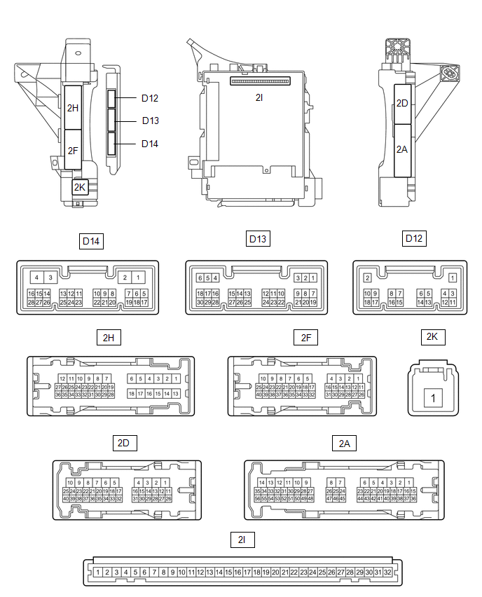
(a) Disconnect the cable from the negative (-) battery terminal.
(b) Disconnect the main body ECU (multiplex network body ECU) connectors.
|
*1 |
DLC3 |
- |
- |
|
*a |
Front view of wire harness connector (to Main Body ECU (Multiplex Network Body ECU)) |
- |
- |
(c) Measure the resistance according to the value(s) in the table below.
Standard Resistance: Bus 2
|
Terminal No. (Symbol) |
Wiring Color |
Terminal Description |
Condition |
Specified Condition |
|---|---|---|---|---|
|
D13-14 (CANH) - D13-13 (CANL) |
GR - W |
HIGH-level CAN bus line - LOW-level CAN bus line |
Cable disconnected from negative (-) battery terminal |
54 to 69 Ω |
|
D13-14 (CANH) - D16-4 (CG) |
GR - W-B |
HIGH-level CAN bus line - Ground |
Cable disconnected from negative (-) battery terminal |
200 Ω or higher |
|
D13-13 (CANL) - D16-4 (CG) |
W - W-B |
LOW-level CAN bus line - Ground |
Cable disconnected from negative (-) battery terminal |
200 Ω or higher |
|
D13-14 (CANH) - D16-16 (BAT) |
GR - B |
HIGH-level CAN bus line - Battery positive (+) |
Cable disconnected from negative (-) battery terminal |
6 kΩ or higher |
|
D13-13 (CANL) - D16-16 (BAT) |
W - B |
LOW-level CAN bus line - Battery positive (+) |
Cable disconnected from negative (-) battery terminal |
6 kΩ or higher |
Standard Resistance: Sub Bus 1
|
Terminal No. (Symbol) |
Wiring Color |
Terminal Description |
Condition |
Specified Condition |
|---|---|---|---|---|
|
D14-9 (CANP) - D14-10 (CANN) |
LG - W |
HIGH-level CAN bus line - LOW-level CAN bus line |
Cable disconnected from negative (-) battery terminal |
108 to 132 Ω |
|
D14-9 (CANP) - D16-4 (CG) |
LG - W-B |
HIGH-level CAN bus line - Ground |
Cable disconnected from negative (-) battery terminal |
200 Ω or higher |
|
D14-10 (CANN) - D16-4 (CG) |
W - W-B |
LOW-level CAN bus line - Ground |
Cable disconnected from negative (-) battery terminal |
200 Ω or higher |
|
D14-9 (CANP) - D16-16 (BAT) |
LG - B |
HIGH-level CAN bus line - Battery positive (+) |
Cable disconnected from negative (-) battery terminal |
6 kΩ or higher |
|
D14-10 (CANN) - D16-16 (BAT) |
W - B |
LOW-level CAN bus line - Battery positive (+) |
Cable disconnected from negative (-) battery terminal |
6 kΩ or higher |
13. CERTIFICATION ECU (SMART KEY ECU ASSEMBLY) (w/ Smart Key System)
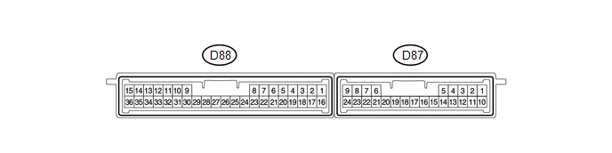
(a) Disconnect the cable from the negative (-) battery terminal.
(b) Disconnect the certification ECU (smart key ECU assembly) connector.
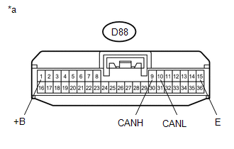
|
*a |
Front view of wire harness connector (to Certification ECU (Smart Key ECU Assembly)) |
(c) Measure the resistance according to the value(s) in the table below.
Standard Resistance
|
Terminal No. (Symbol) |
Wiring Color |
Terminal Description |
Condition |
Specified Condition |
|---|---|---|---|---|
|
D88-9 (CANH) - D88-10 (CANL) |
B - W |
HIGH-level CAN bus line - LOW-level CAN bus line |
Cable disconnected from negative (-) battery terminal |
54 to 69 Ω |
|
D88-9 (CANH) - D88-15 (E) |
B - W-B |
HIGH-level CAN bus line - Ground |
Cable disconnected from negative (-) battery terminal |
200 Ω or higher |
|
D88-10 (CANL) - D88-15 (E) |
W - W-B |
LOW-level CAN bus line - Ground |
Cable disconnected from negative (-) battery terminal |
200 Ω or higher |
|
D88-9 (CANH) - D88-1 (+B) |
B - G |
HIGH-level CAN bus line - Battery positive (+) |
Cable disconnected from negative (-) battery terminal |
6 kΩ or higher |
|
D88-10 (CANL) - D88-1 (+B) |
W - G |
LOW-level CAN bus line - Battery positive (+) |
Cable disconnected from negative (-) battery terminal |
6 kΩ or higher |
14. BRAKE ACTUATOR ASSEMBLY (SKID CONTROL ECU)
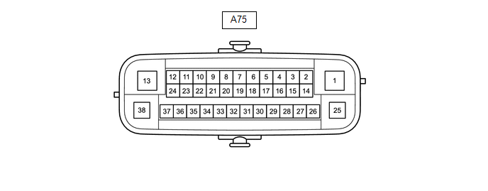
(a) Disconnect the cable from the negative (-) battery terminal.
(b) Disconnect the brake actuator assembly (skid control ECU) connector.
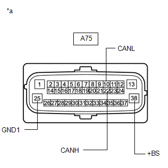
|
*a |
Front view of wire harness connector (to Brake Actuator Assembly (Skid Control ECU)) |
(c) Measure the resistance according to the value(s) in the table below.
Standard Resistance
|
Terminal No. (Symbol) |
Wiring Color |
Terminal Description |
Condition |
Specified Condition |
|---|---|---|---|---|
|
A75-22 (CANH) - A75-10 (CANL) |
R - W |
HIGH-level CAN bus line - LOW-level CAN bus line |
Cable disconnected from negative (-) battery terminal |
54 to 69 Ω |
|
A75-22 (CANH) - A75-25 (GND1) |
R - W-B |
HIGH-level CAN bus line - Ground |
Cable disconnected from negative (-) battery terminal |
200 Ω or higher |
|
A75-10 (CANL) - A75-25 (GND1) |
W - W-B |
LOW-level CAN bus line - Ground |
Cable disconnected from negative (-) battery terminal |
200 Ω or higher |
|
A75-22 (CANH) - A75-38 (+BS) |
R - W |
HIGH-level CAN bus line - Battery positive (+) |
Cable disconnected from negative (-) battery terminal |
6 kΩ or higher |
|
A75-10 (CANL) - A75-38 (+BS) |
W - W |
LOW-level CAN bus line - Battery positive (+) |
Cable disconnected from negative (-) battery terminal |
6 kΩ or higher |
15. STEERING ANGLE SENSOR (SPIRAL CABLE WITH SENSOR SUB-ASSEMBLY)

(a) Disconnect the cable from the negative (-) battery terminal.
(b) Disconnect the steering angle sensor (spiral cable with sensor sub-assembly) connector.
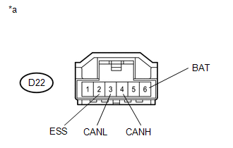
|
*a |
Front view of wire harness connector (to Steering Angle Sensor (Spiral Cable with Sensor Sub-assembly)) |
(c) Measure the resistance according to the value(s) in the table below.
Standard Resistance
|
Terminal No. (Symbol) |
Wiring Color |
Terminal Description |
Condition |
Specified Condition |
|---|---|---|---|---|
|
D22-4 (CANH) - D22-3 (CANL) |
L - Y |
HIGH-level CAN bus line - LOW-level CAN bus line |
Cable disconnected from negative (-) battery terminal |
54 to 69 Ω |
|
D22-4 (CANH) - D22-2 (ESS) |
L - W-B |
HIGH-level CAN bus line - Ground |
Cable disconnected from negative (-) battery terminal |
200 Ω or higher |
|
D22-3 (CANL) - D22-2 (ESS) |
Y - W-B |
LOW-level CAN bus line - Ground |
Cable disconnected from negative (-) battery terminal |
200 Ω or higher |
|
D22-4 (CANH) - D22-6 (BAT) |
L - W |
HIGH-level CAN bus line - Battery positive (+) |
Cable disconnected from negative (-) battery terminal |
6 kΩ or higher |
|
D22-3 (CANL) - D22-6 (BAT) |
Y - W |
LOW-level CAN bus line - Battery positive (+) |
Cable disconnected from negative (-) battery terminal |
6 kΩ or higher |
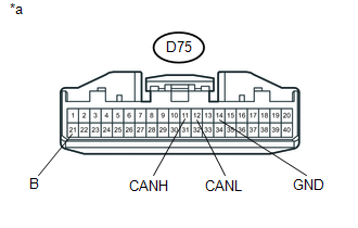
16. AIR CONDITIONING AMPLIFIER ASSEMBLY
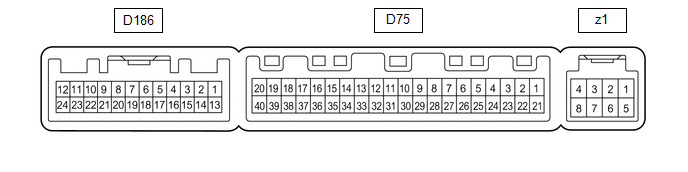
(a) Disconnect the cable from the negative (-) battery terminal.
(b) Disconnect the air conditioning amplifier assembly connector.
|
*a |
Front view of wire harness connector (to Air Conditioning Amplifier assembly) |
(c) Measure the voltage and resistance according to the value(s) in the table below.
Standard Resistance
|
Terminal No. (Symbol) |
Wiring Color |
Terminal Description |
Condition |
Specified Condition |
|---|---|---|---|---|
|
D75-11 (CANH) - D75-12 (CANL) |
G - W |
HIGH-level CAN bus line - LOW-level CAN bus line |
Cable disconnected from negative (-) battery terminal |
54 to 69 Ω |
|
D75-11 (CANH) - D75-14 (GND) |
G- W-B |
HIGH-level CAN bus line - Ground |
Cable disconnected from negative (-) battery terminal |
200 Ω or higher |
|
D75-12 (CANL) - D75-14 (GND) |
W - W-B |
LOW-level CAN bus line - Ground |
Cable disconnected from negative (-) battery terminal |
200 Ω or higher |
|
D75-11 (CANH) - D75-21 (B) |
G - P |
HIGH-level CAN bus line - Battery positive (+) |
Cable disconnected from negative (-) battery terminal |
6 kΩ or higher |
|
D75-12 (CANL) - D75-21 (B) |
W - P |
LOW-level CAN bus line - Battery positive (+) |
Cable disconnected from negative (-) battery terminal |
6 kΩ or higher |
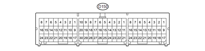
17. AIRBAG SENSOR ASSEMBLY
(a) Disconnect the cable from the negative (-) battery terminal, and wait for at least 90 seconds.
(b) Disconnect the airbag sensor assembly connector.
|
*1 |
DLC3 |
|
*a |
Front view of wire harness connector (to Airbag Sensor Assembly) |
(c) Measure the resistance according to the value(s) in the table below.
Standard Resistance
|
Terminal No. (Symbol) |
Wiring Color |
Terminal Description |
Condition |
Specified Condition |
|---|---|---|---|---|
|
D150-13 (CANH) - D150-22 (CANL) |
B - W |
HIGH-level CAN bus line - LOW-level CAN bus line |
Cable disconnected from negative (-) battery terminal |
54 to 69 Ω |
|
D150-13 (CANH) - D16-4 (CG) |
B - W-B |
HIGH-level CAN bus line - Ground |
Cable disconnected from negative (-) battery terminal |
200 Ω or higher |
|
D150-22 (CANL) - D16-4 (CG) |
W - W-B |
LOW-level CAN bus line - Ground |
Cable disconnected from negative (-) battery terminal |
200 Ω or higher |
|
D150-13 (CANH) - D16-16 (BAT) |
B - B |
HIGH-level CAN bus line - Battery positive (+) |
Cable disconnected from negative (-) battery terminal |
6 kΩ or higher |
|
D150-22 (CANL) - D16-16 (BAT) |
W - B |
LOW-level CAN bus line - Battery positive (+) |
Cable disconnected from negative (-) battery terminal |
6 kΩ or higher |
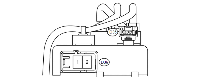
18. STEERING COLUMN ASSEMBLY (POWER STEERING ECU)
(a) Disconnect the cable from the negative (-) battery terminal.
(b) Disconnect the steering column assembly (power steering ECU) connectors.
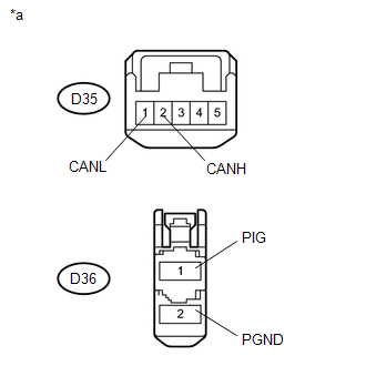
|
*a |
Front view of wire harness connector (to Steering Column Assembly (Power Steering ECU)) |
(c) Measure the resistance according to the value(s) in the table below.
Standard Resistance
|
Terminal No. (Symbol) |
Wiring Color |
Terminal Description |
Condition |
Specified Condition |
|---|---|---|---|---|
|
D35-2 (CANH) - D35-1 (CANL) |
B - W |
HIGH-level CAN bus line - LOW-level CAN bus line |
Cable disconnected from negative (-) battery terminal |
54 to 69 Ω |
|
D35-2 (CANH) - D36-2 (PGND) |
B - W-B |
HIGH-level CAN bus line - Ground |
Cable disconnected from negative (-) battery terminal |
200 Ω or higher |
|
D35-1 (CANL) - D36-2 (PGND) |
W - W-B |
LOW-level CAN bus line - Ground |
Cable disconnected from negative (-) battery terminal |
200 Ω or higher |
|
D35-2 (CANH) - D36-1 (PIG) |
B - B |
HIGH-level CAN bus line - Battery positive (+) |
Cable disconnected from negative (-) battery terminal |
6 kΩ or higher |
|
D35-1 (CANL) - D36-1 (PIG) |
W - B |
LOW-level CAN bus line - Battery positive (+) |
Cable disconnected from negative (-) battery terminal |
6 kΩ or higher |
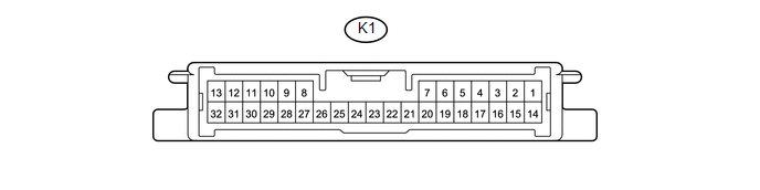
19. 4WD ECU ASSEMBLY (for AWD)
(a) Disconnect the cable from the negative (-) battery terminal.
(b) Disconnect the 4WD ECU assembly connector.
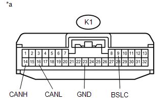
|
*a |
Front view of wire harness connector (to 4WD ECU assembly) |
(c) Measure the resistance according to the value(s) in the table below.
Standard Resistance
|
Terminal No. (Symbol) |
Wiring Color |
Terminal Description |
Condition |
Specified Condition |
|---|---|---|---|---|
|
K1-14 (CANH) - K1-16 (CANL) |
L - W |
HIGH-level CAN bus line - LOW-level CAN bus line |
Cable disconnected from negative (-) battery terminal |
54 to 69 Ω |
|
K1-14 (CANH) - K1-23 (GND) |
L - W-B |
HIGH-level CAN bus line - Ground |
Cable disconnected from negative (-) battery terminal |
200 Ω or higher |
|
K1-16 (CANL) - K1-23 (GND) |
W - W-B |
LOW-level CAN bus line - Ground |
Cable disconnected from negative (-) battery terminal |
200 Ω or higher |
|
K1-14 (CANH) - K1-9 (BSLC) |
L - BE |
HIGH-level CAN bus line - Battery positive (+) |
Cable disconnected from negative (-) battery terminal |
6 kΩ or higher |
|
K1-16 (CANL) - K1-9 (BSLC) |
W - BE |
LOW-level CAN bus line - Battery positive (+) |
Cable disconnected from negative (-) battery terminal |
6 kΩ or higher |
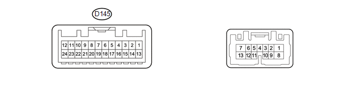
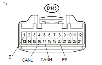
20. COMBINATION METER ASSEMBLY
(a) Disconnect the cable from the negative (-) battery terminal.
(b) Disconnect the combination meter assembly connectors.
|
*a |
Front view of wire harness connector (to Combination Meter Assembly) |
(c) Measure the resistance according to the value(s) in the table below.
Standard Resistance:
|
Terminal No. (Symbol) |
Wiring Color |
Terminal Description |
Condition |
Specified Condition |
|---|---|---|---|---|
|
D145-17 (CANH) - D145-16 (CANL) |
P - W |
HIGH-level CAN bus line - LOW-level CAN bus line |
Cable disconnected from negative (-) battery terminal |
108 to 132 Ω |
|
D145-17 (CANH) - D145-20 (ES) |
P - BR |
HIGH-level CAN bus line - Ground |
Cable disconnected from negative (-) battery terminal |
200 Ω or higher |
|
D145-16 (CANL) - D145-20 (ES) |
W - BR |
LOW-level CAN bus line - Ground |
Cable disconnected from negative (-) battery terminal |
200 Ω or higher |
|
D145-17 (CANH) - D145-1 (B) |
P - W |
HIGH-level CAN bus line - Battery positive (+) |
Cable disconnected from negative (-) battery terminal |
6 kΩ or higher |
|
D145-16 (CANL) - D145-1 (B) |
W - W |
LOW-level CAN bus line - Battery positive (+) |
Cable disconnected from negative (-) battery terminal |
6 kΩ or higher |
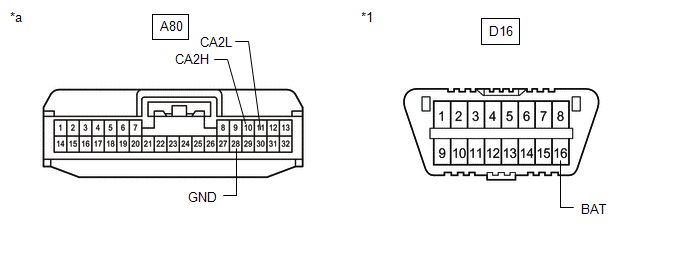
21. DRIVING SUPPORT ECU ASSEMBLY (w/ Toyota Safety Sense P)
(a) Disconnect the cable from the negative (-) battery terminal.
(b) Disconnect the driving support ECU assembly connector.
|
*1 |
DLC3 |
- |
- |
|
*a |
Front view of wire harness connector (to Driving Support ECU Assembly) |
- |
- |
(c) Measure the resistance according to the value(s) in the table below.
Standard Resistance
|
Terminal No. (Symbol) |
Wiring Color |
Terminal Description |
Condition |
Specified Condition |
|---|---|---|---|---|
|
A80-10 (CA2H) - A80-11 (CA2L) |
R - W |
HIGH-level CAN bus line - LOW-level CAN bus line |
Cable disconnected from negative (-) battery terminal |
54 to 69 Ω |
|
A80-10 (CA2H) - A80-28 (GND) |
R - BR |
HIGH-level CAN bus line - Ground |
Cable disconnected from negative (-) battery terminal |
200 Ω or higher |
|
A80-11 (CA2L) - A80-28 (GND) |
W - BR |
LOW-level CAN bus line - Ground |
Cable disconnected from negative (-) battery terminal |
200 Ω or higher |
|
A80-10 (CA2H) - D16-16 (BAT) |
R - B |
HIGH-level CAN bus line - Battery positive (+) |
Cable disconnected from negative (-) battery terminal |
6 kΩ or higher |
|
A80-11 (CA2L) - D16-16 (BAT) |
W - B |
LOW-level CAN bus line - Battery positive (+) |
Cable disconnected from negative (-) battery terminal |
6 kΩ or higher |
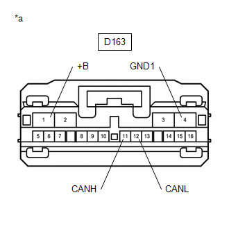
22. PARKING ASSIST ECU (w/ Panoramic View Monitor System)
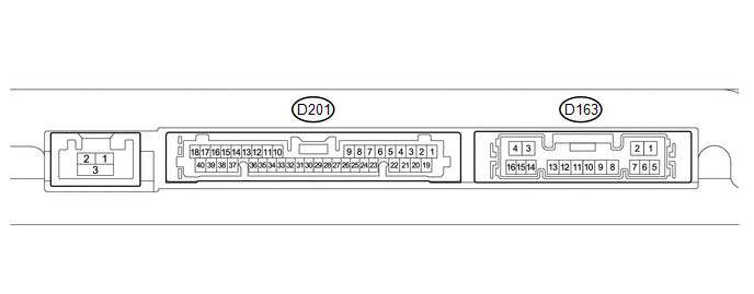
(a) Disconnect the cable from the negative (-) battery terminal.
(b) Disconnect the parking assist ECU connector.
|
*a |
Front view of wire harness connector (to Parking Assist ECU) |
(c) Measure the resistance according to the value(s) in the table below.
Standard Resistance
|
Terminal No. (Symbol) |
Wiring Color |
Terminal Description |
Condition |
Specified Condition |
|---|---|---|---|---|
|
D163-11 (CANH) - D163-12 (CANL) |
L - W |
HIGH-level CAN bus line - LOW-level CAN bus line |
Cable disconnected from negative (-) battery terminal |
54 to 69 Ω |
|
D163-11 (CANH) - D163-4 (GND1) |
L - W-B |
HIGH-level CAN bus line - Ground |
Cable disconnected from negative (-) battery terminal |
200 Ω or higher |
|
D163-12 (CANL) - D163-4 (GND1) |
W - W-B |
LOW-level CAN bus line - Ground |
Cable disconnected from negative (-) battery terminal |
200 Ω or higher |
|
D163-11 (CANH) - D163-1 (+B) |
L - B |
HIGH-level CAN bus line - Battery positive (+) |
Cable disconnected from negative (-) battery terminal |
6 kΩ or higher |
|
D163-12 (CANL) - D163-1 (+B) |
W - B |
LOW-level CAN bus line - Battery positive (+) |
Cable disconnected from negative (-) battery terminal |
6 kΩ or higher |
23. CLEARANCE WARNING ECU ASSEMBLY (w/ Intelligent Parking Assist System)

(a) Disconnect the cable from the negative (-) battery terminal.
(b) Disconnect the clearance warning ECU assembly connector.
|
*1 |
DLC3 |
- |
- |
|
*a |
Front view of wire harness connector (to Clearance Warning ECU Assembly) |
- |
- |
(c) Measure the resistance according to the value(s) in the table below.
Standard Resistance
|
Terminal No. (Symbol) |
Wiring Color |
Terminal Description |
Condition |
Specified Condition |
|---|---|---|---|---|
|
D200-17 (R1) - D200-18 (R2) |
LG - W |
HIGH-level CAN bus line - LOW-level CAN bus line |
Cable disconnected from negative (-) battery terminal |
54 to 69 Ω |
|
D200-17 (R1) - D200-30 (E) |
LG - W-B |
HIGH-level CAN bus line - Ground |
Cable disconnected from negative (-) battery terminal |
200 Ω or higher |
|
D200-18 (R2) - D200-30 (E) |
W - W-B |
LOW-level CAN bus line - Ground |
Cable disconnected from negative (-) battery terminal |
200 Ω or higher |
|
D200-17 (R1) - D16-16 (BAT) |
LG - B |
HIGH-level CAN bus line - Battery positive (+) |
Cable disconnected from negative (-) battery terminal |
6 kΩ or higher |
|
D200-18 (R2) - D16-16 (BAT) |
W - B |
LOW-level CAN bus line - Battery positive (+) |
Cable disconnected from negative (-) battery terminal |
6 kΩ or higher |
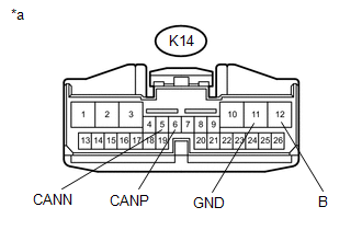
24. POWER BACK DOOR UNIT ASSEMBLY (BACK DOOR ECU) (w/ Power Back Door)

(a) Disconnect the cable from the negative (-) battery terminal.
(b) Disconnect the power back door unit assembly (back door ECU) connector.
|
*a |
Front view of wire harness connector (to Power Back Door Unit Assembly (Back Door ECU)) |
(c) Measure the resistance according to the value(s) in the table below.
Standard Resistance
|
Terminal No. (Symbol) |
Wiring Color |
Terminal Description |
Condition |
Specified Condition |
|---|---|---|---|---|
|
K14-6 (CANP) - K14-5 (CANN) |
B - W |
HIGH-level CAN bus line - LOW-level CAN bus line |
Cable disconnected from negative (-) battery terminal |
54 to 69 Ω |
|
K14-6 (CANP) - K14-11 (GND) |
B - W-B |
HIGH-level CAN bus line - Ground |
Cable disconnected from negative (-) battery terminal |
200 Ω or higher |
|
K14-5 (CANN) - K14-11 (GND) |
W - W-B |
LOW-level CAN bus line - Ground |
Cable disconnected from negative (-) battery terminal |
200 Ω or higher |
|
K14-6 (CANP) - K14-12 (B) |
B - B |
HIGH-level CAN bus line - Battery positive (+) |
Cable disconnected from negative (-) battery terminal |
6 kΩ or higher |
|
K14-5 (CANN) - K14-12 (B) |
W - B |
LOW-level CAN bus line - Battery positive (+) |
Cable disconnected from negative (-) battery terminal |
6 kΩ or higher |
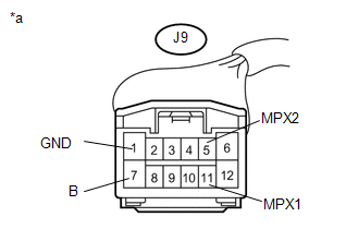
25. SLIDE DOOR MOTOR UNIT LH (w/ Power Slide Door)

(a) Disconnect the cable from the negative (-) battery terminal.
(b) Disconnect the slide door motor unit LH connector.
|
*a |
Front view of wire harness connector (to Slide Door Motor Unit LH) |
(c) Measure the resistance according to the value(s) in the table below.
Standard Resistance
|
Terminal No. (Symbol) |
Wiring Color |
Terminal Description |
Condition |
Specified Condition |
|---|---|---|---|---|
|
J9-11 (MPX1) - J9-5 (MPX2) |
R - W |
HIGH-level CAN bus line - LOW-level CAN bus line |
Cable disconnected from negative (-) battery terminal |
54 to 69 Ω |
|
J9-11 (MPX1) - J9-1 (GND) |
R - W-B |
HIGH-level CAN bus line - Ground |
Cable disconnected from negative (-) battery terminal |
200 Ω or higher |
|
J9-5 (MPX2) - J9-1 (GND) |
W - W-B |
LOW-level CAN bus line - Ground |
Cable disconnected from negative (-) battery terminal |
200 Ω or higher |
|
J9-11 (MPX1) - J9-7 (B) |
R - B-R |
HIGH-level CAN bus line - Battery positive (+) |
Cable disconnected from negative (-) battery terminal |
6 kΩ or higher |
|
J9-5 (MPX2) - J9-7 (B) |
W - B-R |
LOW-level CAN bus line - Battery positive (+) |
Cable disconnected from negative (-) battery terminal |
6 kΩ or higher |
26. SLIDE DOOR MOTOR UNIT RH (w/ Power Slide Door)

(a) Disconnect the cable from the negative (-) battery terminal.
(b) Disconnect the slide door motor unit RH connector.
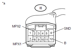
|
*a |
Front view of wire harness connector (to Slide Door Motor Unit RH) |
(c) Measure the resistance according to the value(s) in the table below.
Standard Resistance
|
Terminal No. (Symbol) |
Wiring Color |
Terminal Description |
Condition |
Specified Condition |
|---|---|---|---|---|
|
I8-8 (MPX1) - I8-2 (MPX2) |
R - W |
HIGH-level CAN bus line - LOW-level CAN bus line |
Cable disconnected from negative (-) battery terminal |
54 to 69 Ω |
|
I8-8 (MPX1) - I8-6 (GND) |
R - W-B |
HIGH-level CAN bus line - Ground |
Cable disconnected from negative (-) battery terminal |
200 Ω or higher |
|
I8-2 (MPX2) - I8-6 (GND) |
W - W-B |
LOW-level CAN bus line - Ground |
Cable disconnected from negative (-) battery terminal |
200 Ω or higher |
|
I8-8 (MPX1) - I8-12 (B) |
R - B-R |
HIGH-level CAN bus line - Battery positive (+) |
Cable disconnected from negative (-) battery terminal |
6 kΩ or higher |
|
I8-2 (MPX2) - I8-12 (B) |
W - B-R |
LOW-level CAN bus line - Battery positive (+) |
Cable disconnected from negative (-) battery terminal |
6 kΩ or higher |
27. OUTER MIRROR CONTROL ECU ASSEMBLY LH (w/ Seat Position Memory System)

(a) Disconnect the cable from the negative (-) battery terminal.
(b) Disconnect the outer mirror control ECU assembly LH connector.
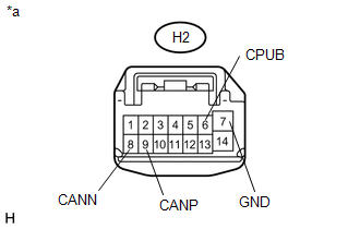
|
*a |
Front view of wire harness connector (to Outer Mirror Control ECU Assembly LH) |
(c) Measure the resistance according to the value(s) in the table below.
Standard Resistance
|
Terminal No. (Symbol) |
Wiring Color |
Terminal Description |
Condition |
Specified Condition |
|---|---|---|---|---|
|
H2-9 (CANP) - H2-8 (CANN) |
P - W |
HIGH-level CAN bus line - LOW-level CAN bus line |
Cable disconnected from negative (-) battery terminal |
54 to 69 Ω |
|
H2-9 (CANP) - H2-7 (GND) |
P - W-B |
HIGH-level CAN bus line - Ground |
Cable disconnected from negative (-) battery terminal |
200 Ω or higher |
|
H2-8 (CANN) - H2-7 (GND) |
W - W-B |
LOW-level CAN bus line - Ground |
Cable disconnected from negative (-) battery terminal |
200 Ω or higher |
|
H2-9 (CANP) - H2-6 (CPUB) |
P - LG |
HIGH-level CAN bus line - Battery positive (+) |
Cable disconnected from negative (-) battery terminal |
6 kΩ or higher |
|
H2-8 (CANN) - H2-6 (CPUB) |
W - LG |
LOW-level CAN bus line - Battery positive (+) |
Cable disconnected from negative (-) battery terminal |
6 kΩ or higher |
28. OUTER MIRROR CONTROL ECU ASSEMBLY RH (w/ Seat Position Memory System)

(a) Disconnect the cable from the negative (-) battery terminal.
(b) Disconnect the outer mirror control ECU assembly RH connector.
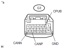
|
*a |
Front view of wire harness connector (to Outer Mirror Control ECU Assembly RH) |
(c) Measure the resistance according to the value(s) in the table below.
Standard Resistance
|
Terminal No. (Symbol) |
Wiring Color |
Terminal Description |
Condition |
Specified Condition |
|---|---|---|---|---|
|
G3-9 (CANP) - G3-8 (CANN) |
GR - W |
HIGH-level CAN bus line - LOW-level CAN bus line |
Cable disconnected from negative (-) battery terminal |
54 to 69 Ω |
|
G3-9 (CANP) - G3-7 (GND) |
GR - W-B |
HIGH-level CAN bus line - Ground |
Cable disconnected from negative (-) battery terminal |
200 Ω or higher |
|
G3-8 (CANN) - G3-7 (GND) |
W - W-B |
LOW-level CAN bus line - Ground |
Cable disconnected from negative (-) battery terminal |
200 Ω or higher |
|
G3-9 (CANP) - G3-6 (CPUB) |
GR - B |
HIGH-level CAN bus line - Battery positive (+) |
Cable disconnected from negative (-) battery terminal |
6 kΩ or higher |
|
G3-8 (CANN) - G3-6 (CPUB) |
W - B |
LOW-level CAN bus line - Battery positive (+) |
Cable disconnected from negative (-) battery terminal |
6 kΩ or higher |
29. FRONT POWER SEAT SWITCH LH (w/ Seat Position Memory System)

(a) Disconnect the cable from the negative (-) battery terminal.
(b) Disconnect the front power seat switch LH connectors.
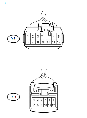
|
*a |
Front view of wire harness connector (to Front Power Seat Switch LH) |
(c) Measure the resistance according to the value(s) in the table below.
Standard Resistance
|
Terminal No. (Symbol) |
Wiring Color |
Terminal Description |
Condition |
Specified Condition |
|---|---|---|---|---|
|
Y9-8 - Y9-7 |
B - W |
HIGH-level CAN bus line - LOW-level CAN bus line |
Cable disconnected from negative (-) battery terminal |
54 to 69 Ω |
|
Y9-8 - Y8-2 |
B - W-B |
HIGH-level CAN bus line - Ground |
Cable disconnected from negative (-) battery terminal |
200 Ω or higher |
|
Y9-7 - Y8-2 |
W - W-B |
LOW-level CAN bus line - Ground |
Cable disconnected from negative (-) battery terminal |
200 Ω or higher |
|
Y9-8 - Y8-7 |
B - W |
HIGH-level CAN bus line - Battery positive (+) |
Cable disconnected from negative (-) battery terminal |
6 kΩ or higher |
|
Y9-7 - Y8-7 |
W - W |
LOW-level CAN bus line - Battery positive (+) |
Cable disconnected from negative (-) battery terminal |
6 kΩ or higher |
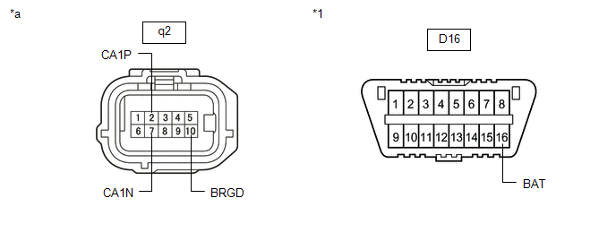
30. BLIND SPOT MONITOR SENSOR RH (w/ Blind Spot Monitor System)

(a) Disconnect the cable from the negative (-) battery terminal.
(b) Disconnect the blind spot monitor sensor RH connector.
|
*1 |
DLC3 |
- |
- |
|
*a |
Front view of wire harness connector (to Blind Spot Monitor Sensor RH) |
- |
- |
(c) Measure the resistance according to the value(s) in the table below.
Standard Resistance
|
Terminal No. (Symbol) |
Wiring Color |
Terminal Description |
Condition |
Specified Condition |
|---|---|---|---|---|
|
q2-2 (CA1P) - q2-7 (CA1N) |
P - W |
HIGH-level CAN bus line - LOW-level CAN bus line |
Cable disconnected from negative (-) battery terminal |
54 to 69 Ω |
|
q2-2 (CA1P) - q2-10 (BRGD) |
P - W-B |
HIGH-level CAN bus line - Ground |
Cable disconnected from negative (-) battery terminal |
200 Ω or higher |
|
q2-7 (CA1N) - q2-10 (BRGD) |
W - W-B |
LOW-level CAN bus line - Ground |
Cable disconnected from negative (-) battery terminal |
200 Ω or higher |
|
q2-2 (CA1P) - D16-16 (BAT) |
P - B |
HIGH-level CAN bus line - Battery positive (+) |
Cable disconnected from negative (-) battery terminal |
6 kΩ or higher |
|
q2-7 (CA1N) - D16-16 (BAT) |
W - B |
LOW-level CAN bus line - Battery positive (+) |
Cable disconnected from negative (-) battery terminal |
6 kΩ or higher |
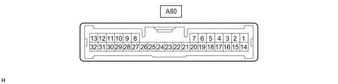
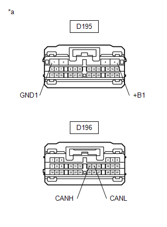
31. RADIO AND DISPLAY RECEIVER ASSEMBLY
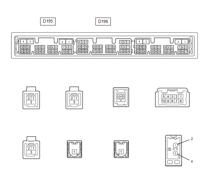
(a) Disconnect the cable from the negative (-) battery terminal.
(b) Disconnect the radio and display receiver assembly connectors.
|
*a |
Front view of wire harness connector (to Radio and Display Receiver Assembly) |
(c) Measure the resistance according to the value(s) in the table below.
Standard Resistance
|
Terminal No. (Symbol) |
Wiring Color |
Terminal Description |
Condition |
Specified Condition |
|---|---|---|---|---|
|
D196-13 (CANH) - D196-14 (CANL) |
BR - W |
HIGH-level CAN bus line - LOW-level CAN bus line |
Cable disconnected from negative (-) battery terminal |
54 to 69 Ω |
|
D196-13 (CANH) - D195-1 (GND1) |
BR - BR |
HIGH-level CAN bus line - Ground |
Cable disconnected from negative (-) battery terminal |
200 Ω or higher |
|
D196-14 (CANL) - D195-1 (GND1) |
W - BR |
LOW-level CAN bus line - Ground |
Cable disconnected from negative (-) battery terminal |
200 Ω or higher |
|
D196-13 (CANH) - D195-4 (+B1) |
BR - SB |
HIGH-level CAN bus line - Battery positive (+) |
Cable disconnected from negative (-) battery terminal |
6 kΩ or higher |
|
D196-14 (CANL) - D195-4 (+B1) |
W - SB |
LOW-level CAN bus line - Battery positive (+) |
Cable disconnected from negative (-) battery terminal |
6 kΩ or higher |
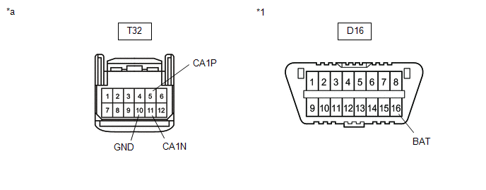
32. FORWARD RECOGNITION CAMERA (w/ Toyota Safety Sense P)

(a) Disconnect the cable from the negative (-) battery terminal.
(b) Disconnect the forward recognition camera connector.
|
*1 |
DLC3 |
- |
- |
|
*a |
Front view of wire harness connector (to Forward Recognition Camera) |
- |
- |
(c) Measure the resistance according to the value(s) in the table below.
Standard Resistance:
|
Terminal No. (Symbol) |
Wiring Color |
Terminal Description |
Condition |
Specified Condition |
|---|---|---|---|---|
|
T32-5 (CA1P) - T32-11 (CA1N) |
G - W |
HIGH-level CAN bus line - LOW-level CAN bus line |
Cable disconnected from negative (-) battery terminal |
54 to 69 Ω |
|
T32-5 (CA1P) - T32-10 (GND) |
G - W-B |
HIGH-level CAN bus line - Ground |
Cable disconnected from negative (-) battery terminal |
200 Ω or higher |
|
T32-11 (CA1N) - T32-10 (GND) |
W - W-B |
LOW-level CAN bus line - Ground |
Cable disconnected from negative (-) battery terminal |
200 Ω or higher |
|
T32-5 (CA1P) - D16-16 (BAT) |
G - B |
HIGH-level CAN bus line - Battery positive (+) |
Cable disconnected from negative (-) battery terminal |
6 kΩ or higher |
|
T32-11 (CA1N) - D16-16 (BAT) |
W - B |
LOW-level CAN bus line - Battery positive (+) |
Cable disconnected from negative (-) battery terminal |
6 kΩ or higher |
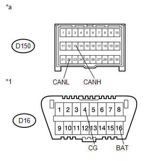
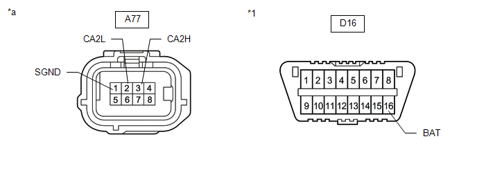
33. MILLIMETER WAVE RADAR SENSOR ASSEMBLY (w/ Toyota Safety Sense P)

(a) Disconnect the cable from the negative (-) battery terminal.
(b) Disconnect the millimeter wave radar sensor assembly connector.
|
*1 |
DLC3 |
- |
- |
|
*a |
Front view of wire harness connector (to Millimeter Wave Radar Sensor Assembly) |
- |
- |
(c) Measure the resistance according to the value(s) in the table below.
Standard Resistance:
|
Terminal No. (Symbol) |
Wiring Color |
Terminal Description |
Condition |
Specified Condition |
|---|---|---|---|---|
|
A77-3 (CA2H) - A77-2 (CA2L) |
GR - W |
HIGH-level CAN bus line - LOW-level CAN bus line |
Cable disconnected from negative (-) battery terminal |
54 to 69 Ω |
|
A77-3 (CA2H) - A77-1 (SGND) |
GR - BR |
HIGH-level CAN bus line - Ground |
Cable disconnected from negative (-) battery terminal |
200 Ω or higher |
|
A77-2 (CA2L) - A77-1 (SGND) |
W - BR |
LOW-level CAN bus line - Ground |
Cable disconnected from negative (-) battery terminal |
200 Ω or higher |
|
A77-3 (CA2H) - D16-16 (BAT) |
GR - B |
HIGH-level CAN bus line - Battery positive (+) |
Cable disconnected from negative (-) battery terminal |
6 kΩ or higher |
|
A77-2 (CA2L) - D16-16 (BAT) |
W - B |
LOW-level CAN bus line - Battery positive (+) |
Cable disconnected from negative (-) battery terminal |
6 kΩ or higher |
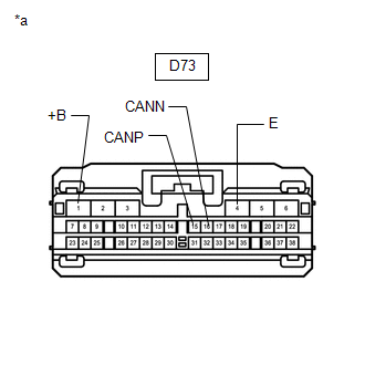
34. DCM (TELEMATICS TRANSCEIVER) (w/ Telematics Transceiver)
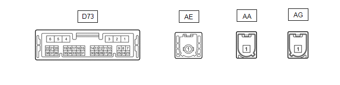
(a) Disconnect the cable from the negative (-) battery terminal.
(b) Disconnect the DCM (telematics transceiver) connector.
|
*a |
Front view of wire harness connector (to DCM (Telematics Transceiver)) |
(c) Measure the resistance according to the value(s) in the table below.
Standard Resistance:
|
Terminal No. (Symbol) |
Wiring Color |
Terminal Description |
Condition |
Specified Condition |
|---|---|---|---|---|
|
D73-15 (CANP) - D73-16 (CANN) |
LG - W |
HIGH-level CAN bus line - LOW-level CAN bus line |
Cable disconnected from negative (-) battery terminal |
54 to 69 Ω |
|
D73-15 (CANP) - D73-4 (E) |
LG - BR |
HIGH-level CAN bus line - Ground |
Cable disconnected from negative (-) battery terminal |
200 Ω or higher |
|
D73-16 (CANN) - D73-4 (E) |
W - BR |
LOW-level CAN bus line - Ground |
Cable disconnected from negative (-) battery terminal |
200 Ω or higher |
|
D73-15 (CANP) - D73-1 (+B) |
LG - SB |
HIGH-level CAN bus line - Battery positive (+) |
Cable disconnected from negative (-) battery terminal |
6 kΩ or higher |
|
D73-16 (CANN) - D73-1 (+B) |
W - SB |
LOW-level CAN bus line - Battery positive (+) |
Cable disconnected from negative (-) battery terminal |
6 kΩ or higher |
35. CHECK REAR TELEVISION CAMERA ASSEMBLY (w/ Panoramic View Monitor System)
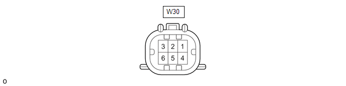
(a) Disconnect the cable from the negative (-) battery terminal.
(b) Disconnect the rear television camera assembly connector.
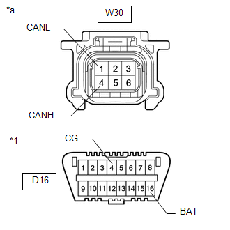
|
*1 |
DLC3 |
|
*a |
Front view of wire harness connector (to Rear Television Camera Assembly) |
(c) Measure the resistance according to the value(s) in the table below.
|
Terminal No. (Symbol) |
Wiring Color |
Terminal Description |
Condition |
Specified Condition |
|---|---|---|---|---|
|
W30-4 (CANH) - W30-1 (CANL) |
P - W |
HIGH-level CAN bus wire - LOW-level CAN bus wire |
Cable disconnected from negative (-) battery terminal |
54 to 69 Ω |
|
W30-4 (CANH) - D16-4 (CG) |
P - W-B |
HIGH-level CAN bus wire - GND |
Cable disconnected from negative (-) battery terminal |
200 Ω or higher |
|
W30-1 (CANL) - D16-4 (CG) |
W - W-B |
LOW-level CAN bus wire - GND |
Cable disconnected from negative (-) battery terminal |
200 Ω or higher |
|
W30-4 (CANH) - D16-16 (BAT) |
P - B |
HIGH-level CAN bus wire - Battery positive (+) |
Cable disconnected from negative (-) battery terminal |
6 kΩ or higher |
|
W30-1 (CANL) - D16-16 (BAT) |
W - B |
LOW-level CAN bus wire - Battery positive (+) |
Cable disconnected from negative (-) battery terminal |
6 kΩ or higher |
|
|
|