| Last Modified: 08-28-2024 | 6.11:8.1.0 | Doc ID: RM1000000019N1R |
| Model Year Start: 2018 | Model: Sienna | Prod Date Range: [11/2017 - ] |
| Title: NAVIGATION / MULTI INFO DISPLAY: NAVIGATION SYSTEM: Mute Signal Circuit between Stereo Component Amplifier and Telematics Transceiver; 2018 - 2020 MY Sienna [11/2017 - ] | ||
|
Mute Signal Circuit between Stereo Component Amplifier and Telematics Transceiver |
DESCRIPTION
The DCM (telematics transceiver) sends a mute signal to the stereo component amplifier assembly.
The stereo component amplifier assembly controls the volume according to the mute signal from the DCM (telematics transceiver).
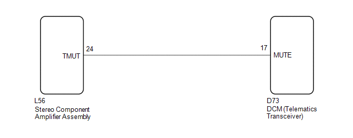
WIRING DIAGRAM
CAUTION / NOTICE / HINT
NOTICE:
If the DCM (telematics transceiver) has been replaced, perform the DCM Activation procedure using the Techstream (See page
![2018 - 2020 MY Sienna [11/2017 - ]; INTRODUCTION: REPAIR INSTRUCTION: INITIALIZATION](/t3Portal/stylegraphics/info.gif) ).
).
PROCEDURE
|
1. |
INSPECT DCM (TELEMATICS TRANSCEIVER) |
|
(a) Measure the voltage according to the value(s) in the table below. Standard Voltage:
Text in Illustration
|
|
| OK |

|
PROCEED TO NEXT SUSPECTED AREA SHOWN IN PROBLEM SYMPTOMS TABLE (See page
|
|

|
2. |
CHECK HARNESS AND CONNECTOR (STEREO COMPONENT AMPLIFIER ASSEMBLY - DCM (TELEMATICS TRANSCEIVER)) |
(a) Disconnect the L56 stereo component amplifier assembly connector.
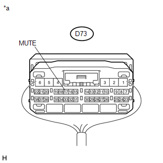
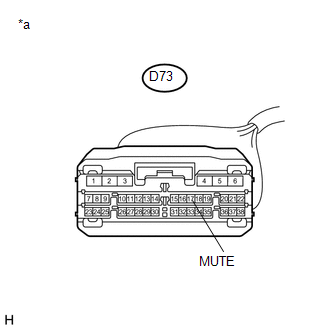
(b) Disconnect the D73 DCM (telematics transceiver) connector.
(c) Measure the resistance according to the value(s) in the table below.
Standard Resistance:
|
Tester Connection |
Condition |
Specified Condition |
|---|---|---|
|
L56-24 (TMUT) - D73-17 (MUTE) |
Always |
Below 1 Ω |
|
L56-24 (TMUT) - Body ground |
Always |
10 kΩ or higher |
| NG |
|
REPAIR OR REPLACE HARNESS OR CONNECTOR |
|
|
3. |
INSPECT STEREO COMPONENT AMPLIFIER ASSEMBLY |
(a) Disconnect the DCM (telematics transceiver) connector.
|
(b) Measure the voltage according to the value(s) in the table below. Standard Voltage:
Text in Illustration
|
|
| OK |
|
| NG |
|
|
|
|