|
Last Modified: 08-28-2024 |
6.11:8.1.0 |
Doc ID: RM100000001980W |
|
Model Year Start: 2018 |
Model: Sienna |
Prod Date Range: [11/2017 -
] |
|
Title: PARK ASSIST / MONITORING: BLIND SPOT MONITOR SYSTEM: C1AB0; Short to +B in Outer Mirror Indicator(Master); 2018 - 2020 MY Sienna [11/2017 - ] |
|
DTC
|
C1AB0
|
Short to +B in Outer Mirror Indicator(Master)
|
DESCRIPTION
This DTC is stored when the blind spot monitor sensor RH detects a +B short in the outer rear view mirror indicator RH.
|
DTC No.
|
DTC Detection Condition
|
Trouble Area
|
|
C1AB0
|
Both of the following conditions are met:
-
Blind spot monitor system is on.
-
The blind spot monitor sensor is not sending voltage to the indicator but the indicator receives voltage above a specified level for a specified period of time.
|
-
Outer rear view mirror RH
-
Outer rear view mirror assembly RH
-
Harness or connector
-
Blind spot monitor sensor RH
|
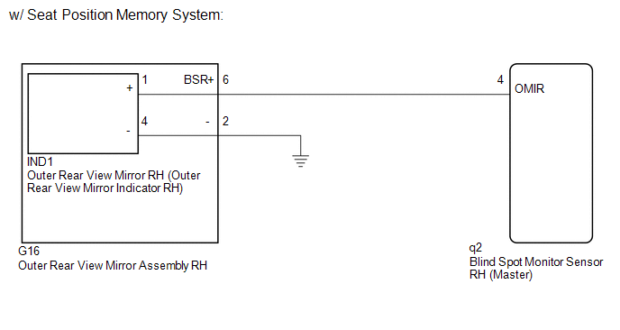
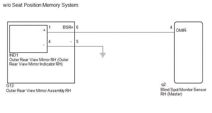
WIRING DIAGRAM
CAUTION / NOTICE / HINT
NOTICE:
When checking for DTCs, make sure that the blind spot monitor system is on.
PROCEDURE
(a) Clear the DTCs (See page
![2018 - 2020 MY Sienna [11/2017 - ]; PARK ASSIST / MONITORING: BLIND SPOT MONITOR SYSTEM: DTC CHECK / CLEAR](/t3Portal/stylegraphics/info.gif) ).
).
(b) Recheck for DTCs and check if the same DTC is output again.
OK:
No DTCs are output.
|
NG
|

|
|
|
2.
|
CHECK HARNESS AND CONNECTOR (BLIND SPOT MONITOR SENSOR RH - OUTER REAR VIEW MIRROR RH (OUTER REAR VIEW MIRROR INDICATOR RH))
|
(a) Disconnect the blind spot monitor sensor RH connector.
|
(b) Measure the voltage according to the value(s) in the table below.
Standard Voltage:
|
Tester Connection
|
Switch Condition
|
Specified Condition
|
|
q2-4 (OMIR) - Body ground
|
Ignition switch ON
|
Below 1 V
|
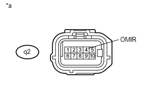
Text in Illustration
|
*a
|
Front view of wire harness connector
(to Blind Spot Monitor Sensor RH)
|
|
|
|
NG
|
|
|
|
|
3.
|
CHECK HARNESS AND CONNECTOR (BLIND SPOT MONITOR SENSOR RH - OUTER REAR VIEW MIRROR RH (OUTER REAR VIEW MIRROR INDICATOR RH))
|
|
(a) Disconnect the IND1 outer rear view mirror RH (outer rear view mirror indicator RH) connector.
|
|
(b) Measure the voltage according to the value(s) in the table below.
Standard Voltage:
|
Tester Connection
|
Switch Condition
|
Specified Condition
|
|
q2-4 (OMIR) - Body ground
|
Ignition switch ON
|
Below 1 V
|
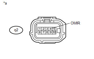
Text in Illustration
|
*a
|
Front view of wire harness connector
(to Blind Spot Monitor Sensor RH)
|
|
NG
|
|
|
|
|
4.
|
CHECK HARNESS AND CONNECTOR (BLIND SPOT MONITOR SENSOR RH - OUTER REAR VIEW MIRROR ASSEMBLY RH)
|
|
(a) Disconnect the G16*1 or G13*2 outer rear view mirror assembly RH connector.
-
*1: w/ Seat Position Memory System
-
*2: w/o Seat Position Memory System
|
|
(b) Measure the voltage according to the value(s) in the table below.
Standard Voltage:
|
Tester Connection
|
Switch Condition
|
Specified Condition
|
|
q2-4 (OMIR) - Body ground
|
Ignition switch ON
|
Below 1 V
|
Text in Illustration
|
*a
|
Front view of wire harness connector
(to Blind Spot Monitor Sensor RH)
|
| NG |

|
REPAIR OR REPLACE HARNESS OR CONNECTOR
|
|