| Last Modified: 08-28-2024 | 6.11:8.1.0 | Doc ID: RM1000000019045 |
| Model Year Start: 2018 | Model: Sienna | Prod Date Range: [11/2017 - ] |
| Title: PARK ASSIST / MONITORING: INTUITIVE PARKING ASSIST SYSTEM: Clearance Sonar Main Switch Circuit; 2018 - 2020 MY Sienna [11/2017 - ] | ||
|
Clearance Sonar Main Switch Circuit |
DESCRIPTION
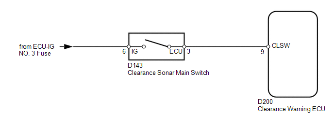
When the clearance sonar main switch turns on, the ON signal is input into the clearance warning ECU.
WIRING DIAGRAM
CAUTION / NOTICE / HINT
NOTICE:
Inspect the fuses for circuits related to this system before performing the following inspection procedure.
PROCEDURE
|
1. |
READ VALUE USING TECHSTREAM (CLEARANCE SONAR MAIN SWITCH) |
(a) Check the Data List for proper functioning of the clearance sonar main switch.
Intuitive P/A
|
Tester Display |
Measurement Item/Range |
Normal Condition |
Diagnostic Note |
|---|---|---|---|
|
Main Switch |
Clearance sonar main switch/OFF or ON |
OFF: Clearance sonar main switch off ON: Clearance sonar main switch on |
- |
OK:
The Techstream display changes according to operation of clearance sonar main switch.
| OK |

|
PROCEED TO NEXT SUSPECTED AREA SHOWN IN PROBLEM SYMPTOMS TABLE |
|

|
2. |
INSPECT CLEARANCE SONAR MAIN SWITCH |
(a) Remove the clearance sonar main switch (See page
![2016 - 2020 MY Sienna [12/2015 - ]; PARK ASSIST / MONITORING: CLEARANCE SONAR MAIN SWITCH: REMOVAL](/t3Portal/stylegraphics/info.gif) ).
).
(b) Measure the resistance according to the value(s) in the table below.
Standard Resistance:
|
Tester Connection |
Switch Condition |
Specified Condition |
|---|---|---|
|
6 (IG) - 3 (ECU) |
Clearance sonar main switch on |
Below 1 Ω |
|
6 (IG) - 3 (ECU) |
Clearance sonar main switch off |
10 kΩ or higher |
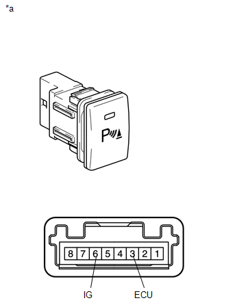
Text in Illustration
|
*a |
Component without harness connected (Clearance Sonar Main Switch) |
| NG |
|
|
|
3. |
CHECK HARNESS AND CONNECTOR (CLEARANCE SONAR MAIN SWITCH - CLEARANCE WARNING ECU AND BATTERY) |
(a) Disconnect the clearance sonar main switch connector.
(b) Disconnect the clearance warning ECU connector.
(c) Measure the voltage according to the value(s) in the table below.
Standard Voltage:
|
Tester Connection |
Switch Condition |
Specified Condition |
|---|---|---|
|
D143-6 (IG) - Body ground |
Ignition switch ON |
11 to 14 V |
|
D143-6 (IG) - Body ground |
Ignition switch off |
Below 1 V |
(d) Measure the resistance according to the value(s) in the table below.
Standard Resistance:
|
Tester Connection |
Condition |
Specified Condition |
|---|---|---|
|
D143-3 (ECU) - D200-9 (CLSW) |
Always |
Below 1 Ω |
|
D143-3 (ECU) or D200-9 (CLSW) - Body ground |
Always |
10 kΩ or higher |
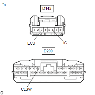
Text in Illustration
|
*a |
Front view of wire harness connector (to Clearance Sonar Main Switch) |
|
*b |
Front view of wire harness connector (to Clearance Warning ECU) |
| OK |
|
| NG |
|
REPAIR OR REPLACE HARNESS OR CONNECTOR |
|
|
|