| Last Modified: 08-28-2024 | 6.11:8.1.0 | Doc ID: RM100000001900S |
| Model Year Start: 2018 | Model: Sienna | Prod Date Range: [11/2017 - ] |
| Title: NAVIGATION / MULTI INFO DISPLAY: NAVIGATION SYSTEM: Reverse Signal Circuit; 2018 - 2020 MY Sienna [11/2017 - ] | ||
|
Reverse Signal Circuit |
DESCRIPTION
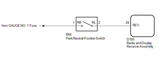
The radio and display receiver assembly receives a reverse signal from the park/neutral position switch.
WIRING DIAGRAM
CAUTION / NOTICE / HINT
NOTICE:
-
When replacing the radio and display receiver assembly, always replace it with a new one. If a radio and display receiver assembly which was installed to another vehicle is used, the following may occur:
- A communication malfunction DTC is stored.
- The radio and display receiver assembly may not operate normally.
- Inspect the fuses for circuits related to this system before performing the following inspection procedure.
PROCEDURE
|
1. |
CHECK VEHICLE SIGNAL (OPERATION CHECK) |
|
(a) Enter the "Vehicle Signal Check Mode" screen. [Refer to Check Vehicle Signal in Operation Check (See page
|
|
![2018 - 2020 MY Sienna [11/2017 - ]; NAVIGATION / MULTI INFO DISPLAY: NAVIGATION SYSTEM: OPERATION CHECK](/t3Portal/stylegraphics/info.gif)
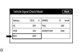
(b) Check that the display changes between ON and OFF according to the shift lever position.
HINT:
This display is updated once per second. As a result, it is normal for the display to lag behind the actual shift lever position.
OK:
|
Shift Lever Position |
Display |
|---|---|
|
R |
ON |
|
Except R |
OFF |
| OK |

|
PROCEED TO NEXT SUSPECTED AREA SHOWN IN PROBLEM SYMPTOMS TABLE (See page
|
|

|
2. |
CHECK RADIO AND DISPLAY RECEIVER ASSEMBLY |
|
(a) Disconnect the radio and display receiver assembly connector. |
|
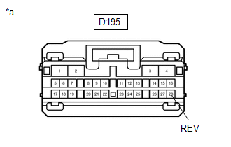
(b) Measure the voltage according to the value(s) in the table below.
Standard Voltage:
|
Tester Connection |
Switch Condition |
Specified Condition |
|---|---|---|
|
D195-28 (REV) - Body ground |
Ignition switch ON, shift lever in R |
7.5 to 14 V |
|
D195-28 (REV) - Body ground |
Ignition switch ON, shift lever not in R |
Below 1 V |
| OK |
|
|
|
3. |
CHECK HARNESS AND CONNECTOR (RADIO AND DISPLAY RECEIVER ASSEMBLY - PARK/NEUTRAL POSITION SWITCH) |
(a) Disconnect the D195 radio and display receiver assembly connector.
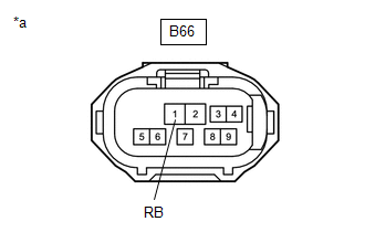
(b) Disconnect the B66 park/neutral position switch connector.
(c) Measure the resistance according to the value(s) in the table below.
Standard Resistance:
|
Tester Connection |
Condition |
Specified Condition |
|---|---|---|
|
D195-28 (REV) - B66-2 (RL) |
Always |
Below 1 Ω |
|
D195-28 (REV) - Body ground |
Always |
10 kΩ or higher |
| NG |
|
REPAIR OR REPLACE HARNESS OR CONNECTOR |
|
|
4. |
CHECK HARNESS AND CONNECTOR (PARK/NEUTRAL POSITION SWITCH - BATTERY) |
|
(a) Disconnect the park/neutral position switch connector. |
|
(b) Measure the voltage according to the value(s) in the table below.
Standard Voltage:
|
Tester Connection |
Switch Condition |
Specified Condition |
|---|---|---|
|
B66-1 (RB) - Body ground |
Ignition switch ON |
11 to 14 V |
Result
|
Result |
Proceed to |
|---|---|
|
OK (for UA80E) |
A |
|
OK (for UA80F) |
B |
|
NG |
C |
| A |
|
| B |
|
| C |
|
REPAIR OR REPLACE HARNESS OR CONNECTOR |
|
|
|